Vapor recovery pump

a technology of vapor recovery pump and piston shaft, which is applied in the direction of piston pump, positive displacement liquid engine, liquid transfer device, etc., can solve the problems of complex and expensive seal between the piston and the piston shaft, increased production and maintenance costs, and complex and expensive connection of the gear wheel

Active Publication Date: 2013-04-23
DRESSER IND INC
View PDF28 Cites 0 Cited by
  • Summary
  • Abstract
  • Description
  • Claims
  • Application Information

AI Technical Summary

Benefits of technology

[0009]It is an object of the present disclosure to provide an improvement to the above techniques and prior art. A particular object is to provide a vapor recovery pump and a fuel dispensing unit of improved construction offering lower production costs and a reduced need for maintenance. Another object is to provide a vapor recovery pump having a smaller size and thereby requiring less mounting space. These and other objects and advantages that will be apparent from the following description are achieved by a vapor recovery pump and a dispensing unit according to the claims. Specific implementations are defined in the dependent claims.
[0010]For example, a vapor recovery pump for a fuel dispensing unit comprises a housing with two chambers each having a vapor inlet valve and a vapor outlet valve, respectively, the chambers being separated by a movable piston arranged to move a distance between a first and a second end position inside the housing for continuously decreasing and increasing the volume of the chambers. A control element is arranged to selectively vary the location of the first end position. This may be an efficient and reliable way of recalibrating the pump and / or changing its vapor pumping capacity. Yet another advantage is that the pump according to some implementations is insensitive to vapor occurring on both sides of the piston.
[0011]Another advantage with a pump according to some implementations is that it may be possible to select the location of the first end position so that vapor flows through one of the chambers while no or basically no vapor flows through the other chamber, when the piston is continuously moved from the location of the first end position to the location of the second end position and back again. In other words, the piston may oscillate between the first and second end positions.

Problems solved by technology

A general problem with existing vapor pumps is that they take up a lot of space and are relatively complex in their arrangement, which causes increased costs both in respect of production and maintenance.
A problem with the device described above is that a complex and expensive seal between the piston and the piston shaft is required in order to prevent vapor and any entrained fuel droplets from entering the crank side of the piston.
Furthermore, the gear wheel connection is complex and expensive.
This permits a coordinated direct operation of the fuel pump and the vapor pump, but again the connection is complex.
In summary, a problem associated with prior art is high production costs due to complex arrangements.
Maintenance is also cumbersome and many of the techniques are sensitive to vapor and fuel occurrence on the wrong side of a piston.
Another problem is that the arrangements are rather voluminous and require a lot of space when mounted inside a fuel dispensing unit.
In the larger chamber, when the piston oscillates between the two end positions, a relatively small change of operating volume may cause a small change of pressure within the chamber.
This small change of pressure may be insufficient for making vapor enter and exit the large chamber through its inlet and outlet valves, and vapor may be only compressed and expanded inside the large chamber.
In the smaller chamber, on the other hand, when the piston oscillates between the two end positions, a relative greater change of operating volume may cause a greater change of pressure within the chamber.

Method used


Image

  • Vapor recovery pump
  • Vapor recovery pump
  • Vapor recovery pump

Examples


Embodiment Construction

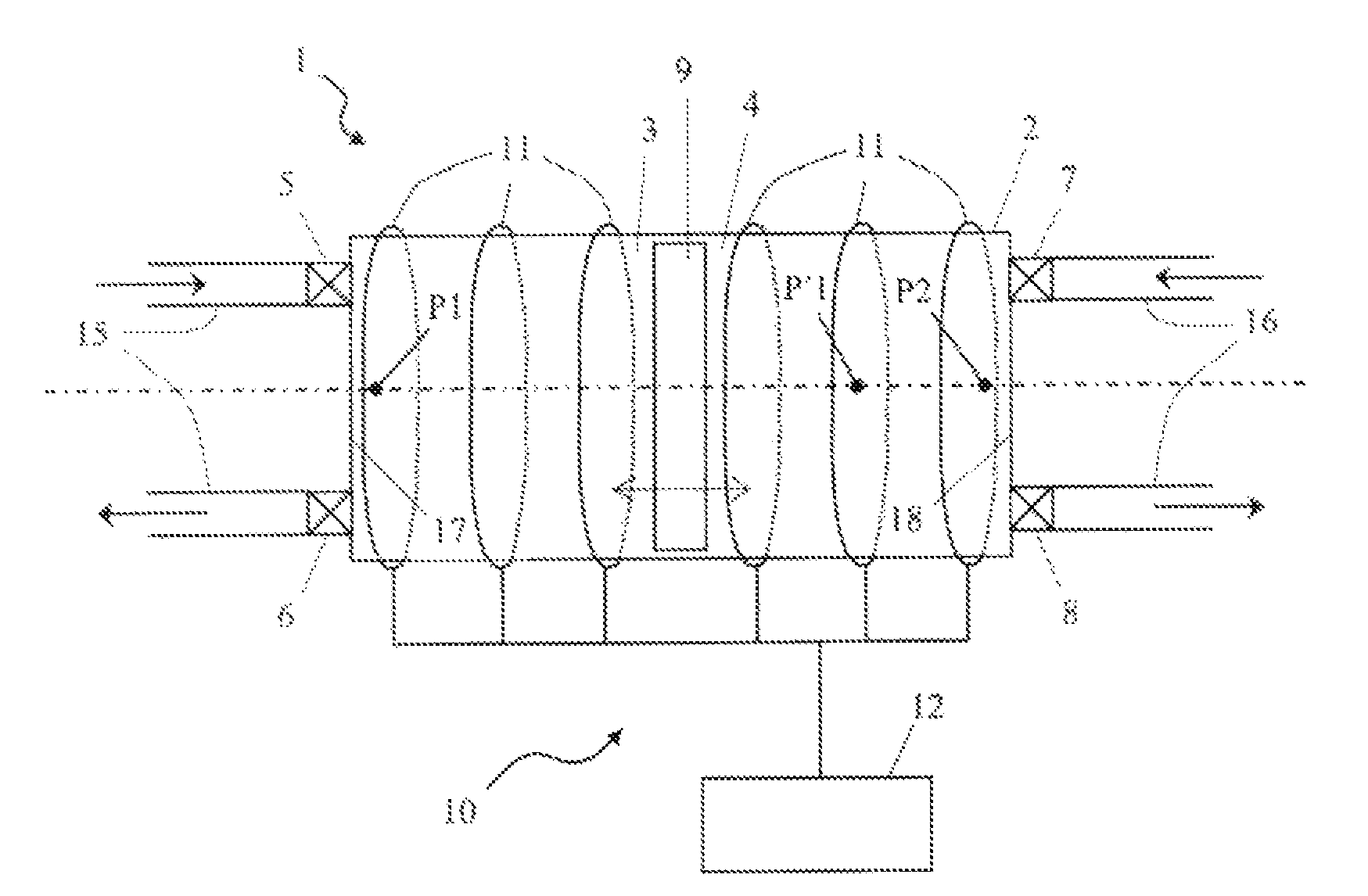
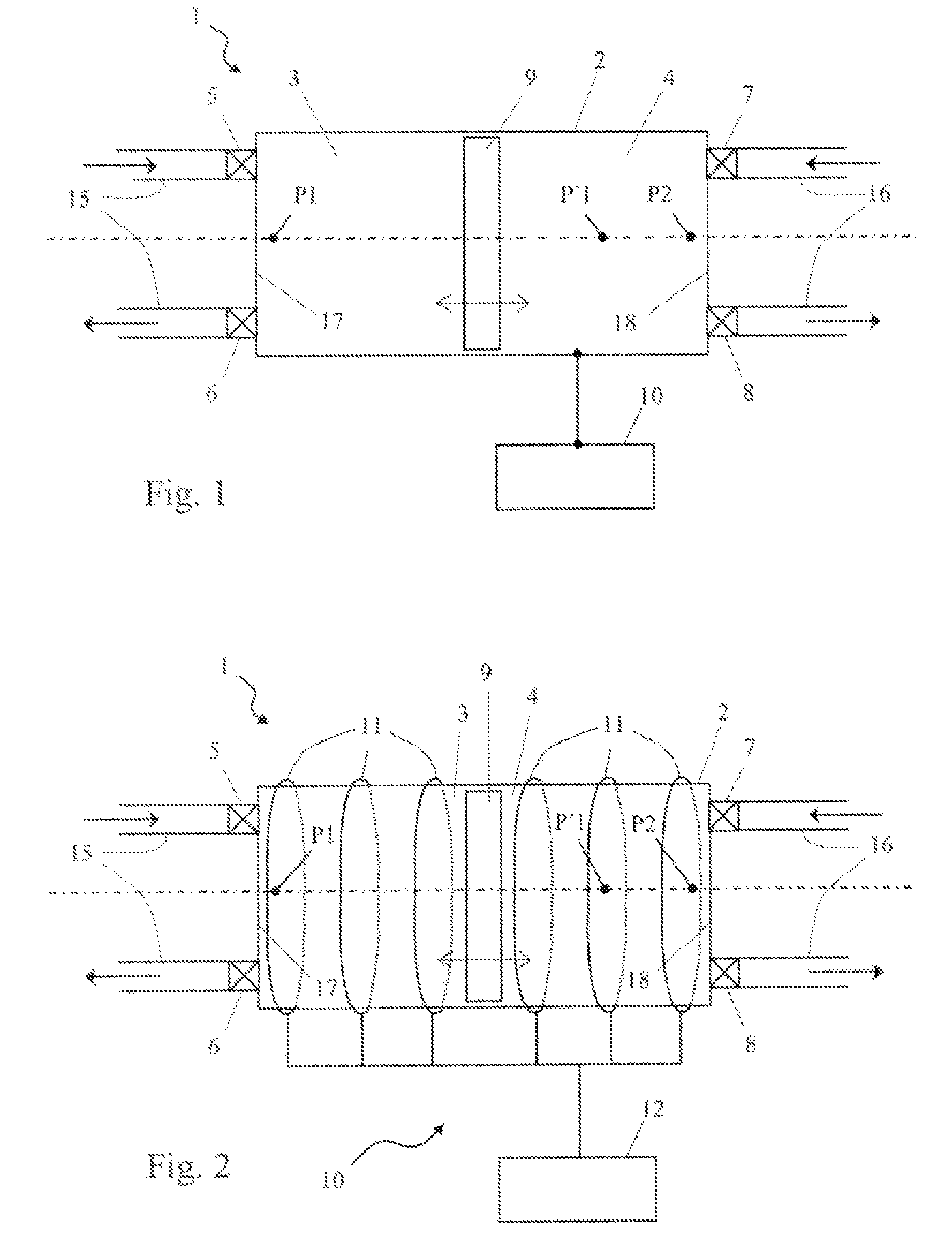
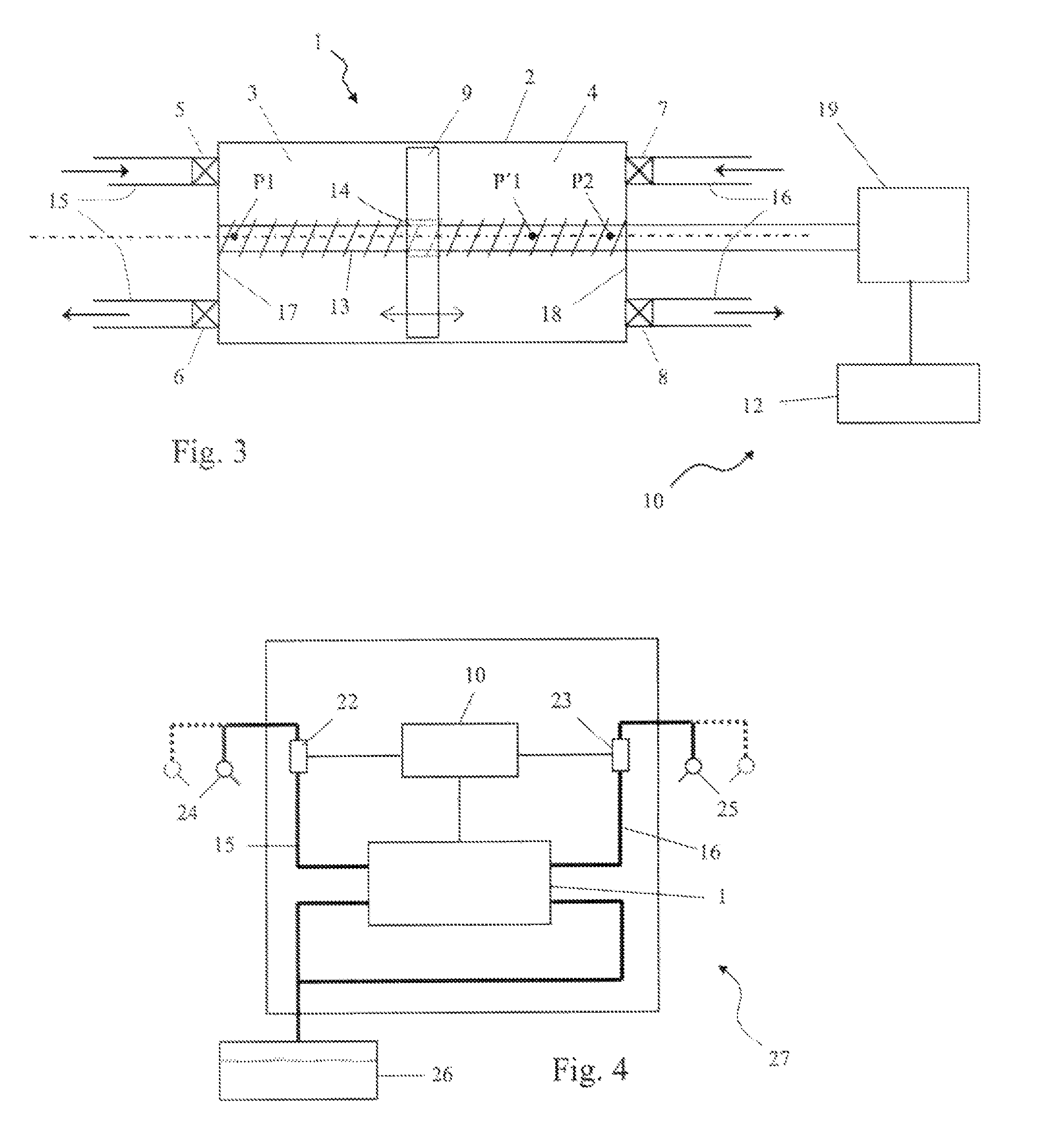
[0029]FIG. 1 shows a vapor recovery pump 1 having a housing 2 that is separated into a first chamber 3 and a second chamber 4. The first chamber 3 has an inlet valve 5, an outlet valve 6 and a chamber end wall 17, while the second chamber 4 also has an inlet valve 7, an outlet valve 8 and a chamber end wall 18. The chambers 3, 4 are separated by a piston 9 arranged inside the housing 2 and substantially seals the chambers 3, 4 to prevent fluid communication there between. Control element 10 is arranged to move the piston 9 along a geometrical axis A between a first outermost end position P1 and a second outermost end position P2 located on the axis A. A first vapor recovery line 15 is connected to the first chamber valves 5-6, and a second vapor recovery line 16 is connected to the second chamber valves 7, 8. Each line 15, 16 generally has an associated upstream vapor suction nozzle and an associated downstream fuel container, from which fuel is fed to the vehicle. This configuratio...


PUM


Abstract

A vapor recovery pump for a fuel dispensing unit, comprising a housing with two chambers each having a vapor inlet valve and a vapor outlet valve, respectively, the chambers being separated by a movable piston arranged to move a distance between a first and a second end position inside the housing for continuously decreasing and increasing the volume of the chambers. A control element is arranged to selectively vary the location of the first end position.

Description

CLAIM OF PRIORITY[0001]This application claims priority under European Patent Application No. 05110415.6, filed on Nov. 7, 2005, the entire contents of which are hereby incorporated by reference.TECHNICAL FIELD[0002]The present invention relates to a vapor recovery pump for a fuel dispensing unit, said pump comprising a housing with two chambers each having a vapor inlet valve and a vapor outlet valve, respectively, the chambers being separated by a movable piston arranged to move a distance between a first and a second end position inside the housing for continuously decreasing and increasing the volume of the chambers.BACKGROUND[0003]When filling the fuel tank of a motor vehicle, it is a common measure to recover the vapor escaping the tank when filling it with liquid fuel. This measure is taken for both safety and environmental reasons. The vapor recovery is achieved, for instance, by arranging a vapor suction nozzle next to the fuel dispensing nozzle of a pistol grip for filling...

Claims


Application Information

Patent Timeline
Patent Type & Authority Patents(United States)
IPC IPC(8): F04B35/04F04B17/04B67D7/04
CPCB67D7/0478F04B19/003F04B35/01F04B35/045F04B37/14F04B49/06
Inventor LARSSON, BENGT I.
Owner DRESSER IND INC
Why Eureka
Try Eureka