Method for producing a protective coating for a component of a turbomachine, the component itself and the respective machine

A technology for protective coatings and turbines, applied in coatings, fire-resistant coatings, engine components, etc., can solve problems such as coating layer loss, barrier value, design tolerances, etc., achieve low production costs and time, and reduce stress and vibration , the effect of high processing quality

Inactive Publication Date: 2010-09-22
NUOVO PIGNONE SPA
View PDF11 Cites 9 Cited by
  • Summary
  • Abstract
  • Description
  • Claims
  • Application Information

AI Technical Summary

Problems solved by technology

[0006] Another disadvantage is that the placement of the multilayer coating layers must be precisely controlled to maintain design tolerances on the finished product while avoiding unwanted imperfections such as marks, delamination of the coating, and loss of the barrier imparted by the coating itself value

Method used


Image

  • Method for producing a protective coating for a component of a turbomachine, the component itself and the respective machine
  • Method for producing a protective coating for a component of a turbomachine, the component itself and the respective machine
  • Method for producing a protective coating for a component of a turbomachine, the component itself and the respective machine

Examples


Embodiment Construction

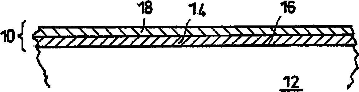
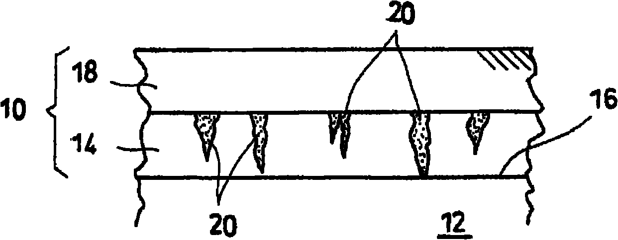
[0038] In the drawings, wherein like numerals correspond to like parts in all the different views, the protective coating 10 ( figure 1 ) for a mechanical component 12 made of a light alloy, in particular but not necessarily an aluminum alloy, the protective coating 10 comprising a corrosion-resistant first coating layer 14 applied to the surface 16 of the mechanical component 12 to be treated, and a second coating layer 18 applied to the first coating layer 14 to resist erosion, wear and high temperatures.

[0039] In an advantageous embodiment of the invention, the first coating layer 14 is obtained by means of anodization in an electrolytic bath by means of an electroplating process.

[0040]In this case, the component 12 is immersed in a vat forming a so-called electroplating bath containing an aqueous solution in the presence of an acid, in which electrodes are immersed to generate an electric current. In this manner, mechanical component 12 is slowly coated with a thin ...


PUM

PropertyMeasurementUnit
thicknessaaaaaaaaaa

Abstract

A method for obtaining a protective coating (10) on a surface to be treated (16) of a light alloy mechanical component (12) of a turbomachine. The method comprises associating a first coating layer (14) resistant to corrosion on the surface to be treated (16) of the mechanical component (12), and associating a second coating layer (18) resistant to erosion, abrasion and high temperatures on the first coating layer (14).

Description

technical field [0001] The invention relates to a method for producing protective coatings for turbomachine components. Furthermore, the invention relates to components to which such a coating is applied, as well as corresponding turbomachines. Background technique [0002] During the development of a new series of steel three-dimensional centrifugal rotors for centrifugal compressors, the need arose to use lighter alloys for the manufacture of the rotors themselves. [0003] A major drawback with regard to the use of lighter alloys for the manufacture of centrifugal rotors is generally that the rotors are susceptible to the erosive effects that fluids moving at high speeds can exert, especially if the fluids contain liquid or solid particles. In the case of rotors made of traditional materials, this erosion phenomenon is usually of negligible amount, but for rotors made of light alloys, the amount of erosion phenomena is very small because of the limited hardness and erosi...

Claims


Application Information

Patent Timeline
Patent Type & Authority Applications(China)
IPC IPC(8): C25D11/04C25D11/18
CPCB05D5/00C25D11/38C25D11/24C25D11/04F01D5/288F05D2230/90B05D2202/25B05D2350/63F05D2260/95C09D5/18Y10T428/31678
Inventor M·加诺兹E·焦尔尼A·阿万兹尼R·保莱蒂I·焦万内蒂
Owner NUOVO PIGNONE SPA
Why Eureka
Try Eureka