Wire Bending Machine

Active Publication Date: 2017-11-02
ADVANCED ORTHODONTIC SOLUTIONS
View PDF18 Cites 9 Cited by
  • Summary
  • Abstract
  • Description
  • Claims
  • Application Information

AI Technical Summary

Benefits of technology

[0012]Generally speaking and pursuant to these various embodiments, a bending machine is provided comprising a wire guide mechanism configured to receive a wire and a bending head. The bending head further comprises, an inner portion, wherein the inner portion includes a guide channel aligned with the wire guide mechanism, and an outer portion, wherein the outer portion includes a cutting edge and one or more bending pins. The outer portion is rotatable about the inner portion. The outer portion is movable from a first position to a second position in which the cutting edge is configured to engage and shear a wire extending through the wire guide mechanism and the guide channel. In one example the cutting edge is the outer circumference of

Problems solved by technology

For instance, the creation of wire grocery carts requires many precise bends which are not easy to manually execute.
Known three dimensional wire bending machines generally have a limited range of rotation for the wire or the bending mechanism.
This limited range of rotation typically results from designs in which cables or hoses related to the actuators or feedback devices restrict the rotation of the bending mechanism, or designs in which a mechanical element simply cannot be rotated beyond a certain range.
A fixed point along the edge cuts the wire, and after multiple cuts the edge dulls such that the cutting mechanism requires more force to cut the wire and forms a less desirable end on the wire.
Thus, because the shearing device degrades it is often designed to be replaceable or removable, req

Method used


Image

  • Wire Bending Machine
  • Wire Bending Machine
  • Wire Bending Machine

Examples


Embodiment Construction

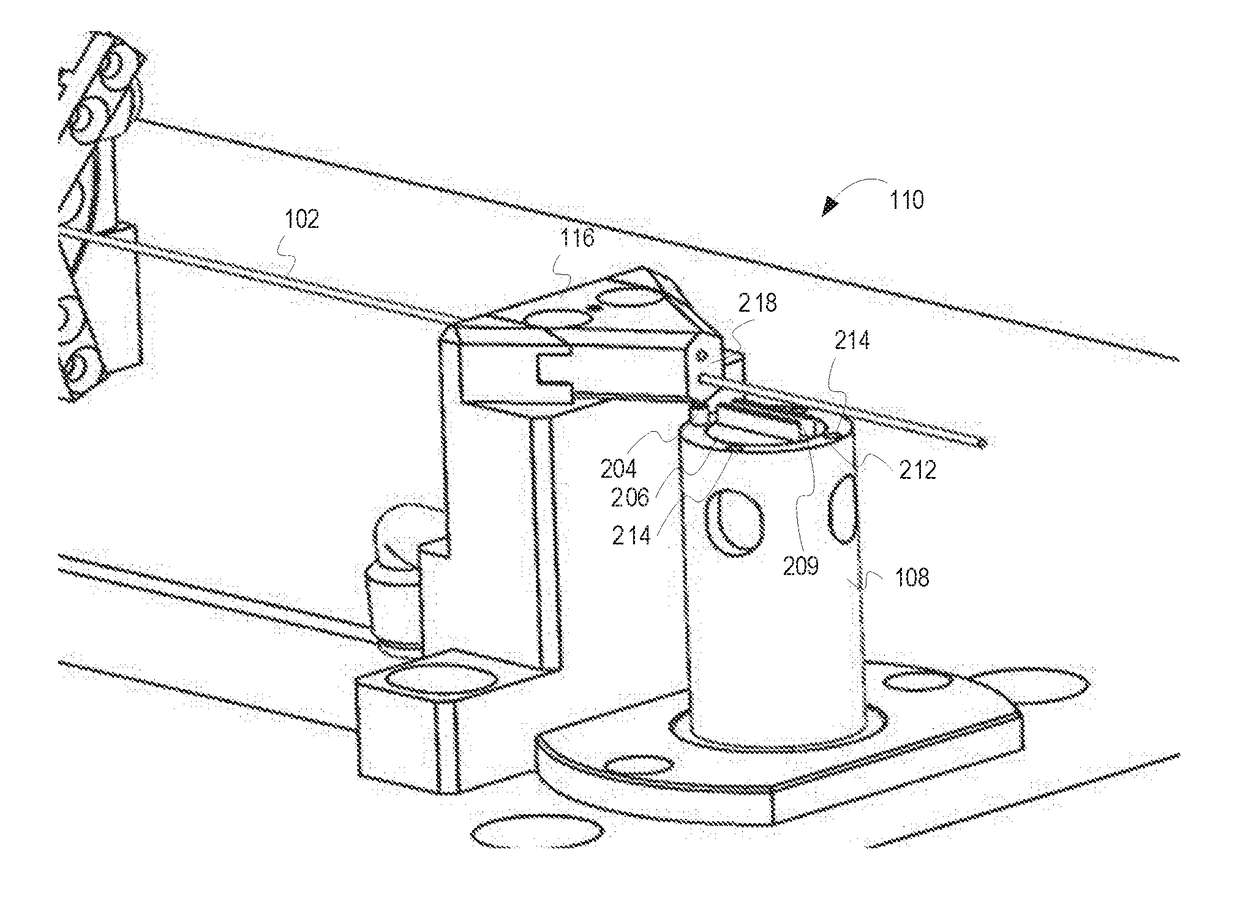
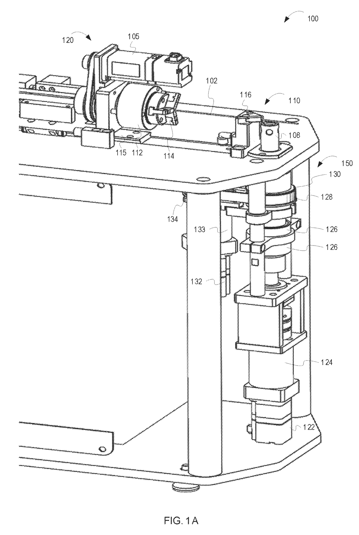
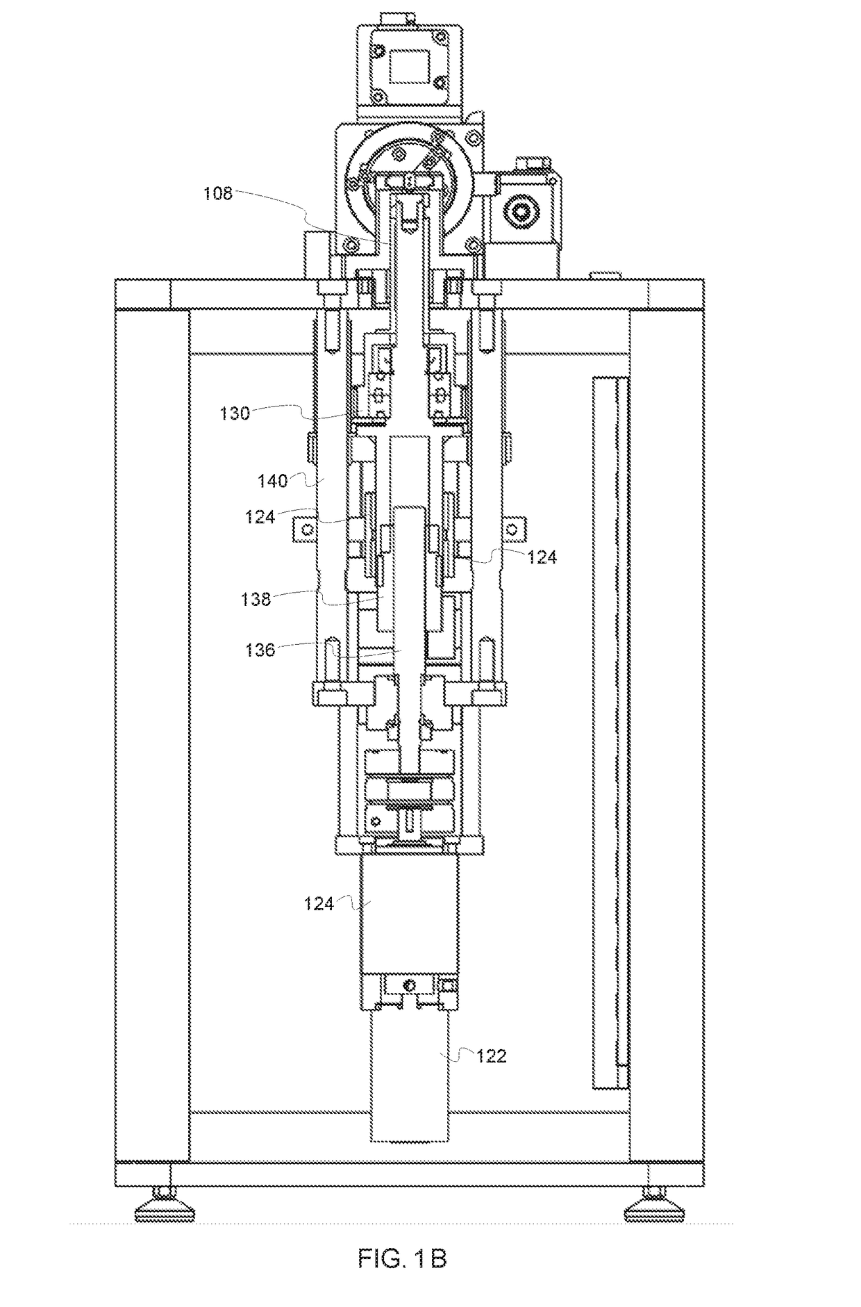
[0042]As previously discussed, current wire bending machines are limited in the manner in which they can manipulate and cut wire. Embodiments of the inventive subject matter include a bending machine that has a greater ability to manipulate wire while bending. Additionally, embodiments of the inventive subject matter include a bending machine that has additional flexibility in cutting wire after it is bent. The bending machines described herein can be modified for use with any type (e.g., material, shape, etc.) of wire and any size (e.g., gauge) wire). FIG. 1 and the related text provide a broad overview of an example wire bending machine, according to some embodiments of the inventive subject matter. Additionally, bending machines similar to those described herein can be used to automate the manufacture of bent wire, as discussed in more detail with respect to FIGS. 10 and 11.

[0043]FIG. 1A is an isometric view of a bending machine 100, according to some embodiments of the inventive...


PUM

PropertyMeasurementUnit
Sizeaaaaaaaaaa

Abstract

A simplified wire bending machine is provided comprising a bending head with an integrated wire cutoff mechanism. The bending head comprises an inner portion, wherein the inner portion includes a wire bending channel; and an outer portion, wherein the outer portion includes a cutting edge and one or more bending pins. The outer portion is rotatable about the inner portion such that a bending pin is capable of bending a wire around the inner portion. Further, the outer portion is movable from a first position to a second position in which the cutting edge is configured to engage and shear a wire.

Description

RELATED APPLICATIONS[0001]This application claims the benefit of U.S. Provisional Application No. 62 / 328,444 filed Apr. 27, 2016, which is hereby incorporated by reference in its entirety.FIELD OF THE INVENTION[0002]This invention relates generally to wire bending and automated wire bending machines. More particularly this invention relates to a simplified wire bending machine.BACKGROUND OF THE INVENTION[0003]Automated wire bending machines are used to create accurate and complex bends in a variety of materials, cross-sectional shapes, and sizes. Automated wire bending machines may be operated, for example, through computer numerical control (CNC). CNC wire bending machines allow a user to design a shape using a computer or other processing device, and have the machine create the shape consistently according to a part program. By automating the wire-forming process, complicated parts can be made beyond the capabilities of ordinarily skilled human craftsmen. Further, CNC wire bending...

Claims


Application Information

Patent Timeline
IPC IPC(8): B21F1/00B21F23/00B21F11/00
CPCB21F1/00B21F23/00B21F11/00B21F1/008
Inventor SUTO, TONYGRAPSAS, CONSTANTINECISON, PIOTR
Owner ADVANCED ORTHODONTIC SOLUTIONS
Why Eureka
Try Eureka