Fluted Rotary Cutting Tool

a technology end mills, which is applied in the field of rotary cutting tools, can solve the problems of undesirable occurrence, poor tool performance in terms of life expectancy and workpiece quality, and considerable performance decay

Inactive Publication Date: 2007-12-27
DE BOER TOOLS
View PDF14 Cites 25 Cited by
  • Summary
  • Abstract
  • Description
  • Claims
  • Application Information

AI Technical Summary

Benefits of technology

[0020]It is another object of the present invention to increase tool life.
[0021]It is a further object of the present invention to improve workpiece quality.

Problems solved by technology

Conventional rotary cutting tools perform adequately at conventional speeds (RPM) and feeds, however, at speeds and feeds higher than conventional, which is desirable for productivity, considerable performance decay is experienced.
This performance decay is directly attributable to the presence and magnitude of vibration, specifically resonant vibration, as cutting force increases.
The occurrence of uncontrolled resonant vibration inevitably results in a condition commonly referred to as “chatter,” which results in poor tool performance both in terms of life expectancy and workpiece quality.
This is an undesirable occurrence.
The primary limiting factor of tools being made with an interrupting variable such as irregular flute form and / or irregular radial position is that the helical path that defines any of the peripheral cutting edges around the circumference is in fact a straight line segment or combination of straight line segments when the helical path is unrolled into a two-dimensional plane.
The problems associated with resonant vibrations have not been satisfactorily solved by the prior art.
Such vibrations, along with associated heat and wear, are detrimental to a long tool life.
While new coating technologies have successfully addressed the issues of heat and wear by introducing a variety of metal, ceramic and chemical substrates, the concern involving resonant vibrations has not been eliminated by the prior art.

Method used


Image

  • Fluted Rotary Cutting Tool
  • Fluted Rotary Cutting Tool
  • Fluted Rotary Cutting Tool

Examples


first embodiment

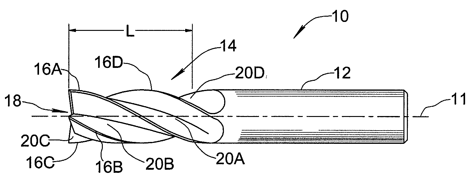
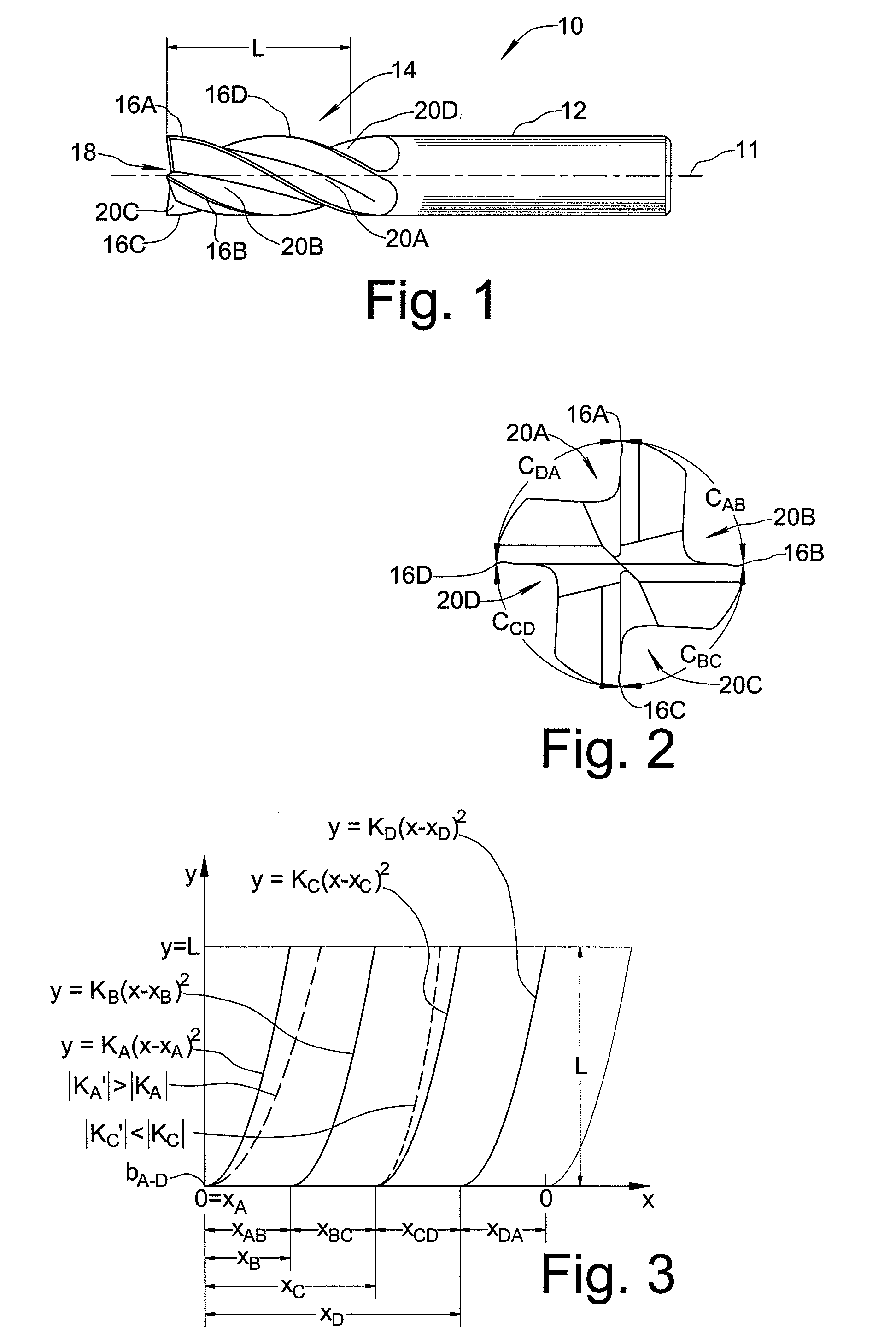
[0032]FIG. 3 is a schematic development view providing a two-dimensional representation of cutting edges 16A-16D in accordance with the present invention. The two-dimensional representation may be thought of as a plot that would result from inking each cutting edge 16A-16D and rolling end mill 10 along a flat surface to leave a mark where each cutting edge contacts the flat surface. The X-axis represents the circumferential distance as end mill 10 is rotated about axis 11 from a starting position as shown in FIG. 2, while the Y-axis represents distance along the flute length starting at cutting end 18 and moving toward shank 12. In accordance with the present invention, cutting edges 16A-16D are formed such that they each present a quadratic curve when represented in a two-dimensional schematic development view. As may be understood, a helical cutting edge will present a single straight line segment characterized by a single helix angle in such a schematic development view, while a ...

second embodiment

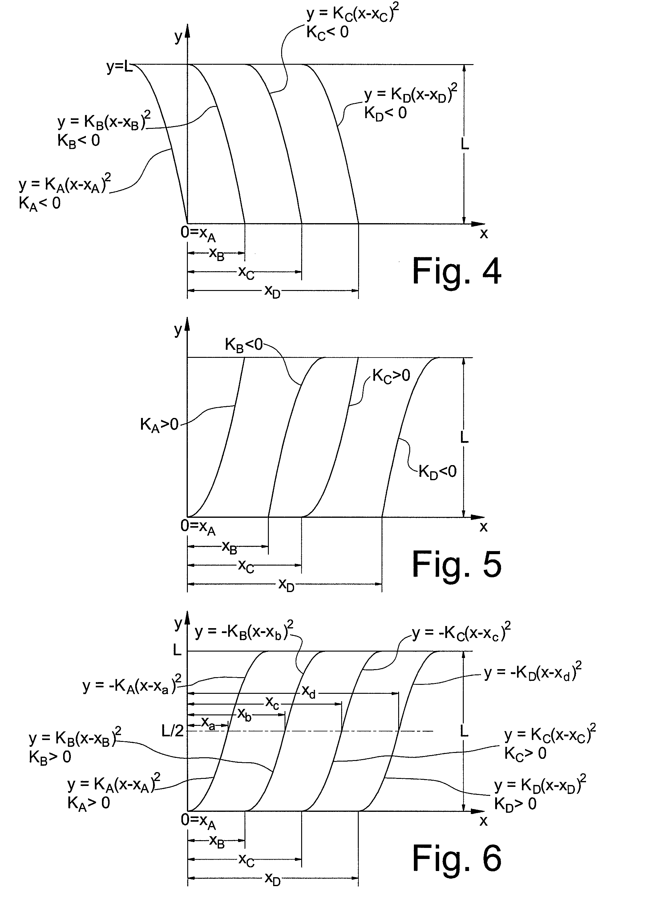
[0036]FIG. 4 is a schematic development view similar to that of FIG. 3 illustrating a cutting tool formed in accordance with the present invention. The embodiment of FIG. 4 differs from that of FIG. 3 in that the scaling constants KA through KD are all negative values, such that the respective curves corresponding to cutting edges 16A-16D have a concave rather than convex shape when viewed along a positive y (axial) direction. Again, the circumferential index values and magnitudes of scaling constants KA through KD may be equal or may vary from cutting edge to cutting edge.

third embodiment

[0037]The schematic development view of FIG. 5 illustrates a third embodiment wherein at least one of the cutting edges has a positive scaling constant and at least one other of the cutting edges has a negative scaling constant. In particular, cutting edges 16A and 16C each have a positive cutting scaling constant (KA and KC, respectively), while cutting edges 16B and 16D each have a negative scaling constant (KB and KD, respectively). It is apparent from FIG. 5 that such an embodiment provides circumferential indexing between cutting edges that varies along effective flute length L.

[0038]FIG. 6 depicts a compound quadratic curve embodiment wherein each cutting edge is formed so as to present a pair of quadratic curve portions in schematic development view. In the axial range from cutting end 18 (y=0) to the mid-point of the effective flute length (y=L / 2), the cutting edges 16A-16D present parabolic curve portions in schematic development view according to the respective equations

y=...


PUM


Abstract

A rotary cutting tool comprises a shank extending along an axis of rotation of the cutting tool and a fluted portion adjacent the shank, the fluted portion having an effective flute length and a plurality of peripheral cutting edges indexed about the axis of rotation. At least one of the plurality of peripheral cutting edges is formed such that a two-dimensional representation of the peripheral cutting edge in schematic development view follows a quadratic curve over the effective flute length.

Description

FIELD OF THE INVENTION[0001]This invention relates generally to rotary cutting tools for milling operations, and in particular to fluted end mills having a plurality of peripheral cutting edges.BACKGROUND OF THE INVENTION[0002]In conventional rotary cutting tools, the peripheral cutting edges are designed to be equally spaced in order to allow even loading on the tool body as a whole. For this reason, the flutes of conventional cutting tools are of the same size and shape which allows equal load distribution among the cutting edges.[0003]In general, rotary cutting tools are designed with multiple flutes spaced symmetrically around the circumference of the tool where the flutes run along a partial length of the tool ending at the tool shank. The tool shank is the portion of the tool that is mounted in a machine tool and the fluted portion is the portion of the tool that engages the workpiece. The total number of flutes may vary, and the flutes may be formed to extend either parallel ...

Claims


Application Information

Patent Timeline
Patent Type & Authority Applications(United States)
IPC IPC(8): B23C5/02
CPCB23C5/10B23C2210/0485Y10T407/1948B23C2210/282B23C2250/16B23C2210/203
Inventor DE BOER, GARY
Owner DE BOER TOOLS
Why Eureka
Try Eureka