
Drilling tool

a technology of drilling tool and cutting tool, which is applied in the direction of turning apparatus, cutting machine, stone-like material working apparatus, etc., can solve the problems of conflicting goals between the percusive capacity and the cutting capacity of the lips, and achieve the effect of improving the cutting capacity and increasing the tool li

Active Publication Date: 2006-02-21
HAWERA PROBST
View PDF23 Cites 26 Cited by
  • Summary
  • Abstract
  • Description
  • Claims
  • Application Information

AI Technical Summary

Benefits of technology

"The invention is a drilling tool with improved cutting and percussion capacity by optimizing the geometry of the lips. The tool has a pyramidal point in the center region and outer regions with different point angles to match the stresses in each region. The design also includes a bevel with a concave or convex profile to match the tool and workpiece. The pyramidal point can be designed in a dome shape to prevent wear. These design features improve the tool's performance and longevity."

Problems solved by technology

This means that, in each region of the lip, there is a conflict of goals between the percussive capacity and the cutting capacity of the lips.

Method used


Image

  • Drilling tool
  • Drilling tool
  • Drilling tool

Examples


Embodiment Construction

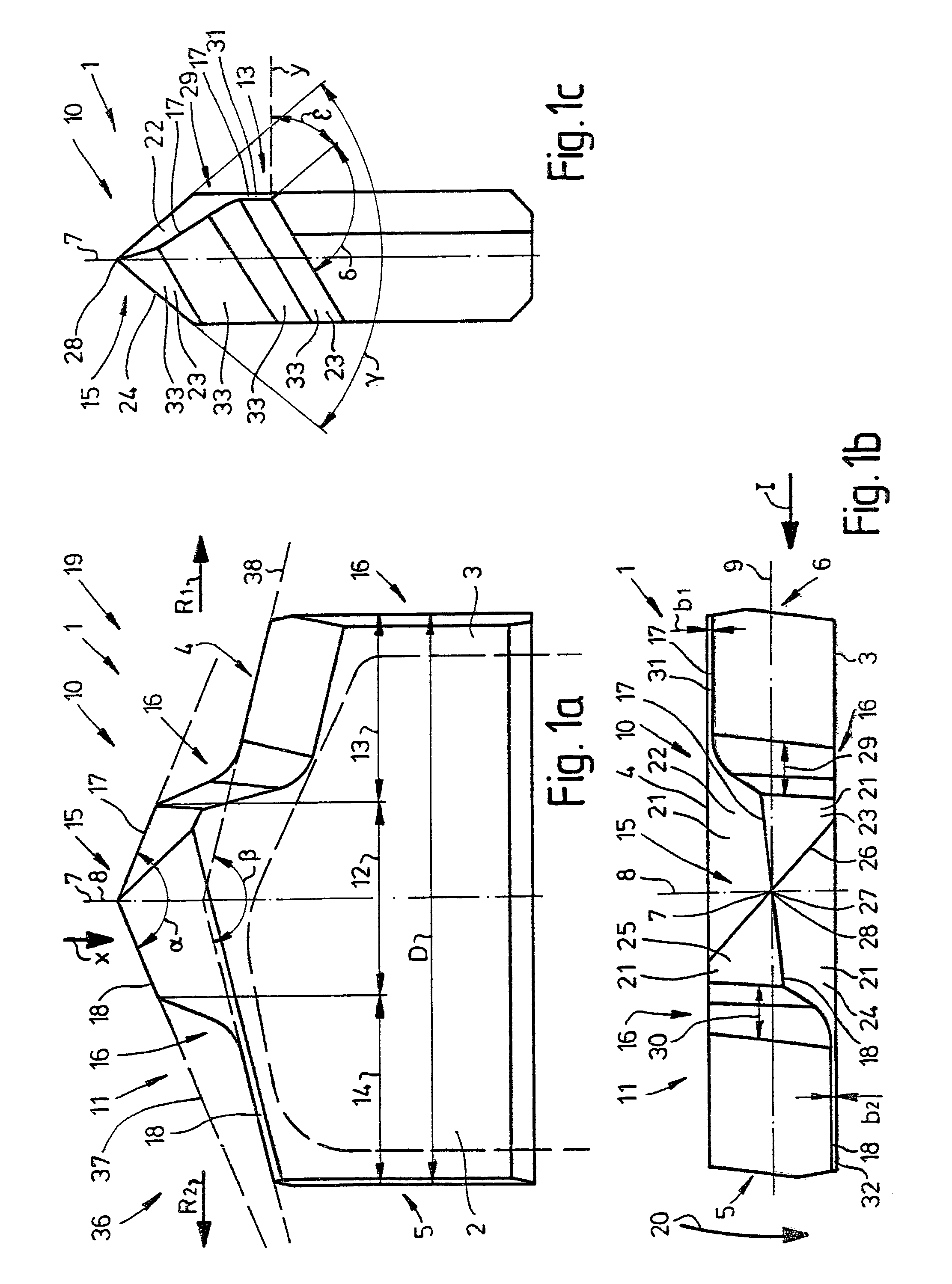
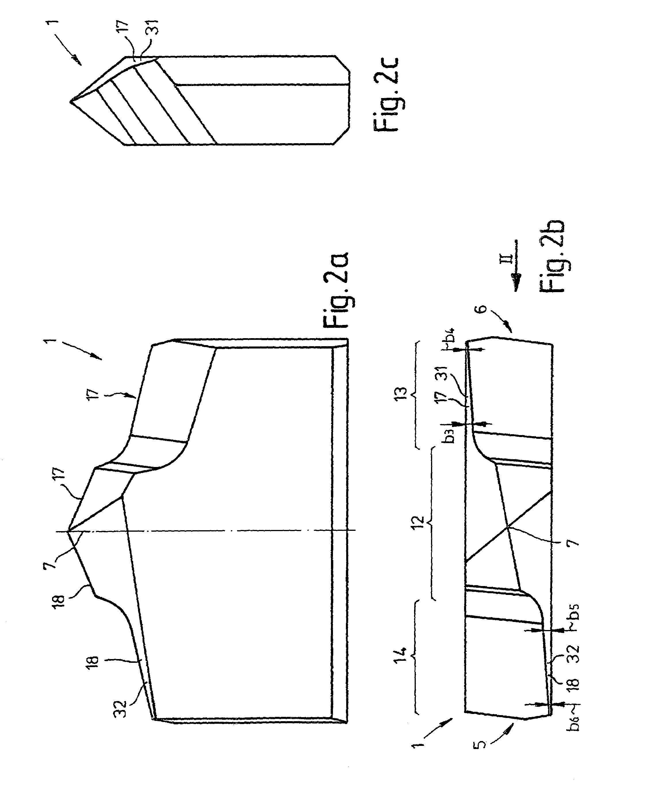
[0046]The drilling tool according to the invention is designated below as “tool”. The carbide cutting tips shown in FIGS. 1a to 6d are also to be understood as a cutaway detail representation of a one-piece tool.

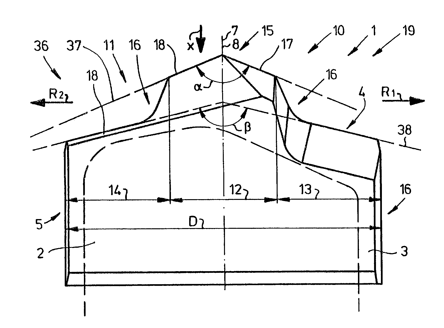
[0047]A cutting tip 1 is shown in side view in FIG. 1a. The cutting tip 1 has an effective diameter D and, inserted into a drill shank 2 indicated by broken lines, forms a complete drilling tool 36 with the latter. In this case, the cutting tip 1 is accommodated or held in the drill shank 2. The drill shank 2 encloses parallel side surfaces 3, 4 and allows further side surfaces 5, 6 of the cutting tip 1 to project freely in the radial direction beyond the drill shank 2. Passing through the cutting tip 1 is a tool longitudinal center axis 7, at which a transverse center plane 8 and a longitudinal center plane 9 intersect at right angles (also see FIG. 1b). Starting from the tool longitudinal center axis 7, lips 10, 11 run in radial directions R1, R2. The cutting tip 1 is subd...


PUM

PropertyMeasurementUnit
widthaaaaaaaaaa
widthaaaaaaaaaa
widthaaaaaaaaaa

Abstract

The invention relates to a drilling tool (36), in particular for working concrete, rock, masonry and suchlike materials, having a single- or multi-edge tool head with at least one cutting body (1) which comprises a central region (12) which is designed in a roof shape, has rake faces and flanks and is defined laterally by two outer regions (13, 14) set back in the effective direction of the drill. In this case, the ground surfaces of the central region (12) form a pyramidal point (15) while avoiding the formation of a chisel edge.

Description

BACKGROUND OF THE INVENTION[0001]The invention relates to a drilling tool having a single- or multi-edge tool head with at least one cutting body, the cutting body having a central region which is designed in a roof shape with rake faces and flanks, and two outer regions set back relative to the central region in a drilling direction of the drill, one outer region being positioned on either side of the central region in a direction perpendicular to the drilling direction.[0002]Conventional drilling tools and in particular rock drills consist of a drill shank with a clamping end and of a drill head which in side view has a gabel-shaped cutting element which is preferably designed as a carbide tip (see, for example, FIG. 1 of EP 0 452 255 B1).[0003]DE 100 38 039 A1 discloses such a drilling tool. This drilling tool, as cutting element, has a carbide tip which has a centering section lying radially on the inside and sections which lie on the outside and are stepped relative to the cent...

Claims


Application Information

Patent Timeline
Patent Type & Authority Patents(United States)
IPC IPC(8): B23B51/02B28D1/14E21B10/44E21B10/58
CPCB23B51/02E21B10/445E21B10/58B28D1/146B23B2226/75B23B2251/04B23B2251/14Y10T408/9065Y10T408/9098
Inventor MOSER, BERNHARDWIDMANN, RAINERLANG, MARCO
Owner HAWERA PROBST
Learn More