
Web cutting device

a cutting device and web technology, applied in the direction of thin material processing, metal working apparatus, article delivery, etc., can solve the problems of high cost of the device, and achieve the effect of cost-effectiveness, reliable operation and more reliable operation

Inactive Publication Date: 2006-10-05
VALMET TECH INC
View PDF5 Cites 9 Cited by
  • Summary
  • Abstract
  • Description
  • Claims
  • Application Information

AI Technical Summary

Benefits of technology

[0009] The object of the invention is especially to provide a device which is cost-effective, reliable in operation, and space-saving.
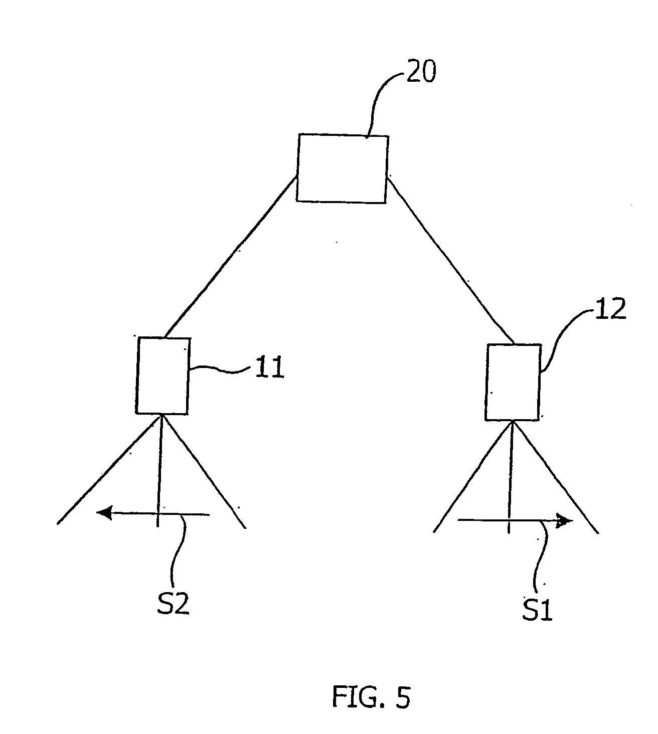
[0010] The device for cutting / cross-cutting a web according to the invention has at least two cutting members, for example, high-pressure water nozzles, laser-cutting members or cutting knives arranged in the device so that, in the cutting situation, power is transmitted with one actuator to both / each cutting member so that the cutting members move in the cross-direction of the web, for example, from the middle of the web towards the edges, that is, in directions opposite to each other, for example, in a mirror image-like manner, when the actuator is operated. Then, considerable advantages are achieved, because a smaller number of components are required for the device, its operation is more reliable when one actuator operates both nozzle units. In addition, need for maintenance is reduced, and obviously, manufacturing costs are lower. Furthermore, the device takes considerably less space in the running direction of the web (machine direction) than arrangements known from prior art.
[0015] The device according to the invention may also be implemented in connection with cutting units moved in place by turning with one actuator mechanically or optically, and the cutting energy is advantageously provided, for example, directly with electricity. In that case, the cutting members are placed in the device so that they are pivoted, which means that the actuator is used for producing a rotating movement around the pivot mechanically or optically by means of a directing mechanism of a cutting beam, thus enabling the web to be cut.
[0017] When using an embodiment of the invention comprising more than two cutting members, an extremely quick web cross-cutting operation is achieved.

Problems solved by technology

A problem of web-cutting devices known from prior art, especially of water cutting devices, has been that two nozzle units are usually used in cutting, which units cut a wedge-shaped tip in the web starting from the middle of the web and proceeding to the web edges, both nozzle units being provided with their own actuators, which means that the device has had high costs.

Method used


Image

  • Web cutting device
  • Web cutting device
  • Web cutting device

Examples


Embodiment Construction

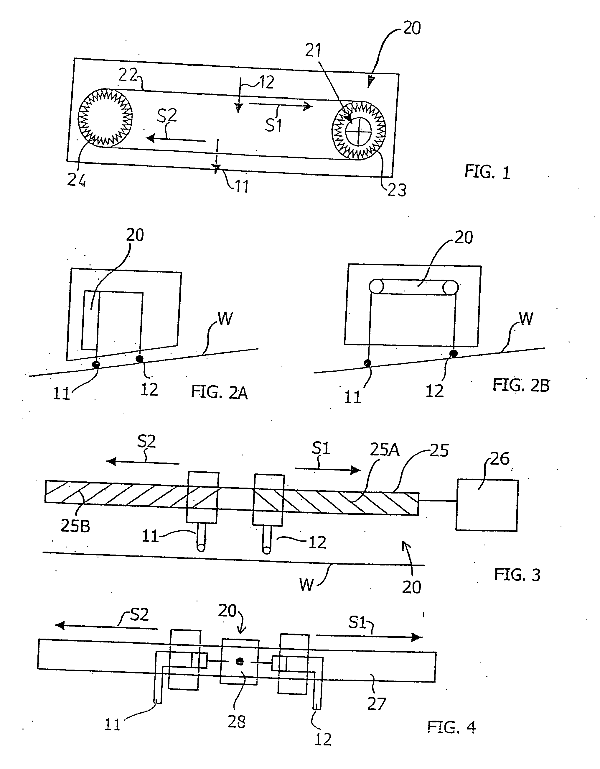
[0025]FIG. 1 depicts an embodiment relating to a water cutting device which has two high-pressure water nozzles 11, 12 fastened to the same toothed belt 22, to the different sides of pulleys 23, 24 rotating the belt 22, the nozzles 11, 12 moving in opposite directions S1, S2 in the cross-direction of the web when the belt 22 is moved via a drive 21.

[0026]FIG. 2A schematically shows an arrangement of the embodiment shown in FIG. 1, placed so that a common actuator 20 for the nozzles 11, 12 is placed in the vertical position in relation to the web W.

[0027]FIG. 2B schematically shows an arrangement of the embodiment shown in FIG. 1 so that the common actuator 20 for the nozzles 11, 12 is placed in the horizontal direction in relation to the web W.

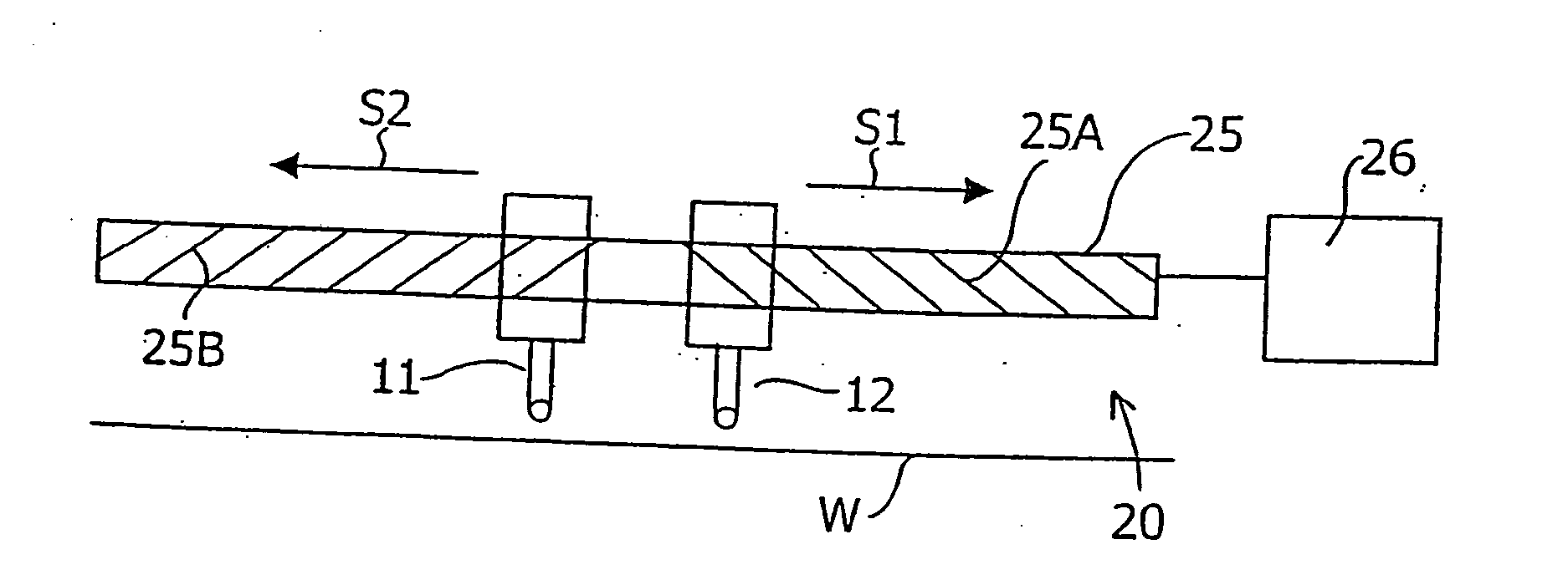
[0028]FIG. 3 schematically shows an embodiment of the invention in which the cutting members 11, 12 are placed on a ball-race screw 25 such that threads 25A, 25B of the ball-race screw 25 go in different directions, so that when turning the...


PUM

PropertyMeasurementUnit
volumeaaaaaaaaaa
pressureaaaaaaaaaa
widthaaaaaaaaaa

Abstract

A device for cutting a web with at least two cutting members for cutting / cross-cutting the web in the cross-direction and producing a cross-cut. The cutting members having a common actuator which moves the cutting members in directions apposite to each other in the cross-direction of the web.

Description

CROSS REFERENCES TO RELATED APPLICATIONS [0001] This application claims priority on Finnish Application No. U20050105, Filed Mar. 31, 2005, the disclosure of which is incorporated by reference herein. STATEMENT AS TO RIGHTS TO INVENTIONS MADE UNDER FEDERALLY SPONSORED RESEARCH AND DEVELOPMENT [0002] Not applicable. BACKGROUND OF THE INVENTION [0003] The present invention relates to a web cutting device. The present invention relates especially to the cutting / cross-cutting of a web taking place in connection with the reeling of a fibre web, such as a paper or board web, when the reeling of the web is changed from a full roll to a new roll. The invention also relates to the web cutting / cross-cutting of a web, a fibre web, for example, a paper or board web, taking place in connection with web threading, in which a leader strip is cut from a full-width web, which leader strip is fed through the machine or part of the machine, after which the web is spread to full width. [0004] In contin...

Claims


Application Information

Patent Timeline
Patent Type & Authority Applications(United States)
IPC IPC(8): B26D3/00B26F3/00B26D1/04B26D11/00B65H35/04
CPCB26D1/045B26D11/00B26F3/004B65H35/04B65H2301/51512B65H2403/52B65H2220/09Y10T83/0591Y10T83/364
Inventor TYNKKYNEN, TOPIPITKANEN, TATUPESONEN, RAIMOVESTERINEN, KALEVIKOJO, TEPPOLANNES, PETTERI
Owner VALMET TECH INC
Learn More