
Bearing with oil film thickness measuring device

Inactive Publication Date: 2006-10-24
DAIDO METAL CO LTD
View PDF4 Cites 2 Cited by
  • Summary
  • Abstract
  • Description
  • Claims
  • Application Information

AI Technical Summary

Benefits of technology

[0008]Also, according to the above-described oil film thickness measuring device, since an optical fiber is used in the sensor portion, the sensor mounting portion takes up less mounting space, and also the degree of freedom of mounting position is high. Further, because of transmission by light, an advantage of being not affected by electrical noise is offered.

Problems solved by technology

However, in these methods, because of a drawback in that although the measurement accuracy of displacement is high, the zero point (origin) drifts, the absolute value of an oil film thickness cannot be measured.

Method used


Image

  • Bearing with oil film thickness measuring device
  • Bearing with oil film thickness measuring device
  • Bearing with oil film thickness measuring device

Examples


Embodiment Construction

[0025]One embodiment of the present invention will now be described with reference to the accompanying drawings.

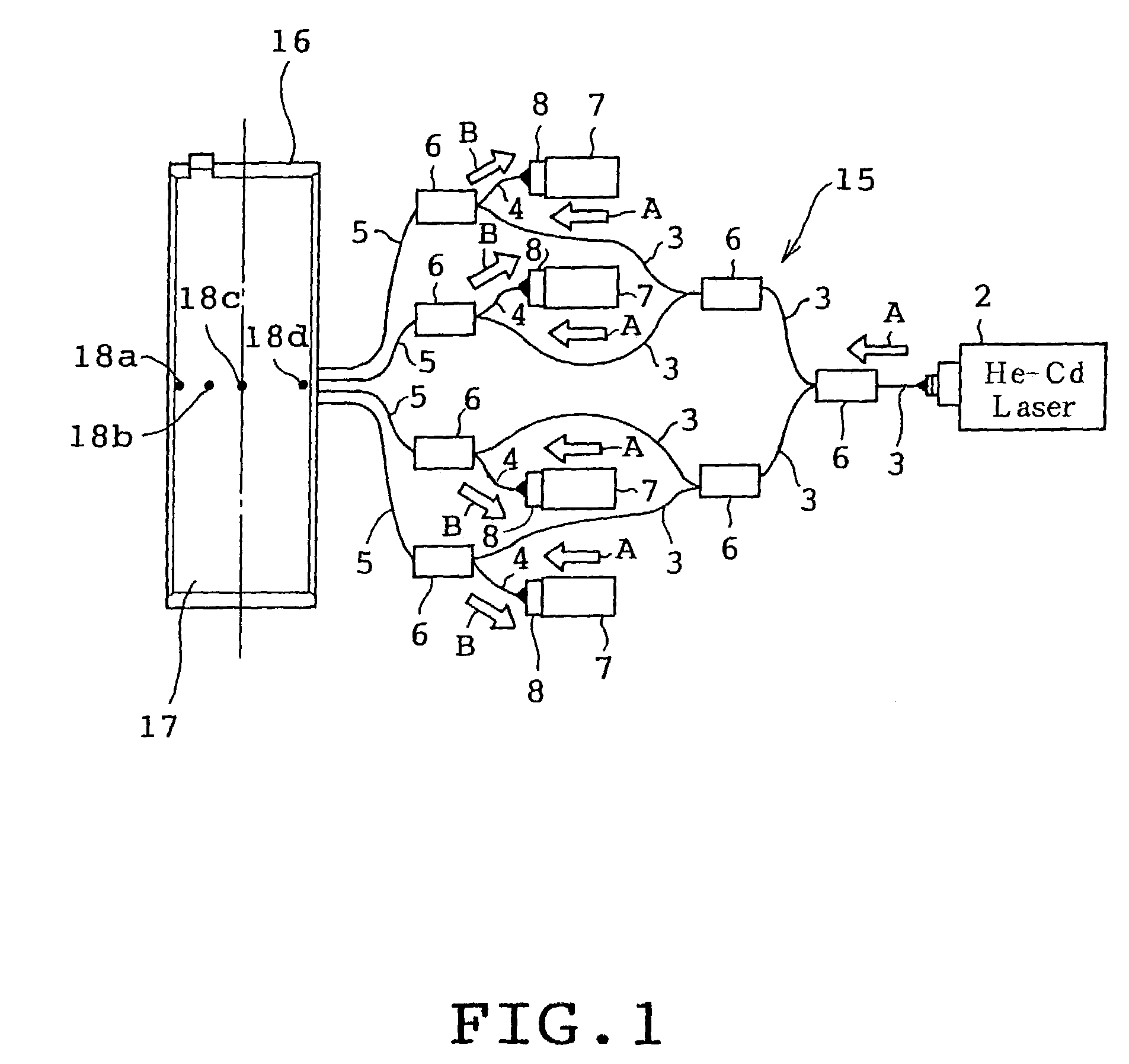
[0026]First, a measurement principle of an oil film thickness measuring device will be described with reference to FIGS. 5A and 5B. In FIG. 5A, an oil film thickness measuring device 1 includes a laser beam generator 2 constituting laser beam generating means, an approach-route optical fiber 3, a return-route optical fiber 4, a common optical fiber 5 which is used as both an approach-route optical fiber and a return-route optical fiber, an optical fiber coupler 6 which connects the approach-route optical fiber 3, the return-route optical fiber 4, and the common optical fiber 5 in a Y shape, a photomultiplier tube 7 constituting fluorescence intensity detecting means, and an optical filter 8 provided on the inlet side of the photomultiplier tube 7.

[0027]The laser beam generator 2, which is a He—Cd laser generator in this case, generates a laser beam with a wavelength of 442...


PUM


Abstract

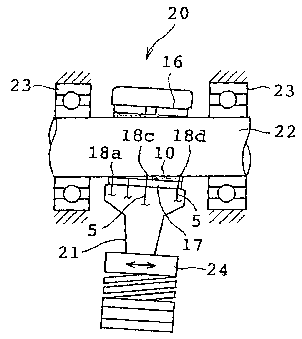
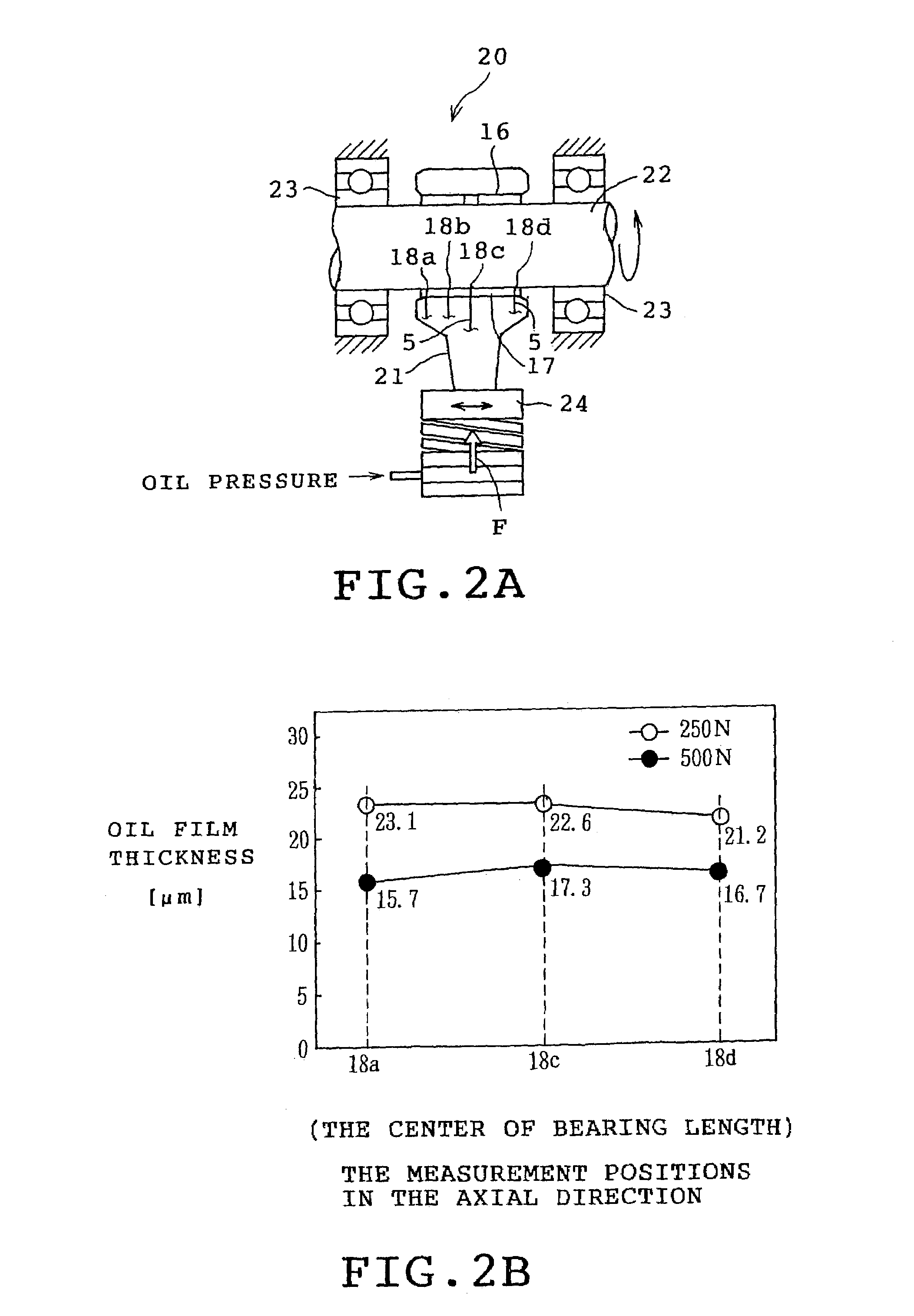
A bearing with an oil film thickness measuring device in which sensor portions at distal ends of four common optical fibers are connected to sensor mounting portions formed at four positions in an axial direction of a bearing body. A lubricating oil containing a fluorescent agent is supplied to a sliding surface of the bearing body. A laser beam generated from a laser beam generator is branched into four beams, which are applied to an oil film on a sliding surface through each of sensor portions. Fluorescence generated by the fluorescent agent in the oil film, passing through a return-route optical fiber, is introduced into a photomultiplier tube, and is detected. Since the fluorescence intensity detected by the photomultiplier tube is proportional to the thickness of oil film, the absolute value of oil film thickness can be measured. In this case, the oil film thickness can be measured at four positions.

Description

CROSS-REFERENCE TO RELATED APPLICATIONS[0001]This application claims priority based on Japanese Application No. 2002-051465, filed Feb. 27, 2002.FIELD OF THE INVENTION[0002]The present invention relates to a bearing with an oil film thickness measuring device which measures a thickness of an oil film formed on a sliding surface.BACKGROUND OF THE INVENTION[0003]Conventionally, as a method of measuring a thickness of an oil film formed on a sliding surface of, for example, a bearing, a capacitance type device, an eddy current type device, or the like have been used. However, in these methods, because of a drawback in that although the measurement accuracy of displacement is high, the zero point (origin) drifts, the absolute value of an oil film thickness cannot be measured.SUMMARY OF THE INVENTION[0004]The present invention has been achieved in view of the above situations, and accordingly an object thereof is to provide a beating with an oil film thickness measuring device capable of...

Claims


Application Information

Patent Timeline
IPC IPC(8): G01B11/26G01B11/06F16C17/24F16C41/00G01N21/64
CPCF16C17/24G01B11/06G01N21/643
Inventor NAKAYAMA, KEIKATAGIRI, TAKESHIOKAMOTO, YUTAKASHIBAYAMA, TAKAYUKI
Owner DAIDO METAL CO LTD
Learn More