Ignition coil with separating wall

a technology of ignition coil and separation wall, which is applied in the direction of transformer/inductance details, inductance, electrical equipment, etc., can solve the problems of ignition coil internal dielectric failure, potential dielectric breakdown from secondary windings to steel laminations, and cracks in the encapsulate, so as to prevent crack propagation, prevent dielectric breakdown, and minimize crack propagation

Inactive Publication Date: 2007-04-24
FORD GLOBAL TECH LLC
View PDF13 Cites 6 Cited by
  • Summary
  • Abstract
  • Description
  • Claims
  • Application Information

AI Technical Summary

Benefits of technology

[0005]The present invention provides an ignition coil for an internal combustion engine that minimizes the propagation of cracks in the encapsulate material surrounding the components of the ignition coil. In one embodiment, the ignition coil comprises a housing, an outer core, an inner coil, and a coil assembly. The housing includes a bottom wall connected to an outer wall extending around the periphery of the housing. The outer core is positioned inside the outer wall, while the inner core is positioned inside the outer core. The coil assembly includes a primary winding and a secondary winding concentrically positioned relative to each other. The coil assembly is mounted to the inner core and positioned inside the outer core. The housing further includes an inner wall extending along the inner periphery of the outer core and positioned between the outer core and the coil assembly. In this way, the inner wall can prevent propagation of cracks into the encapsulate material surrounding the coil assembly, thereby preventing dielectric breakdown. The inner wall also provides a dielectric barrier between the secondary coil and the laminations.
[0006]According to more detailed aspects, the inner wall separates the outer core from direct contact with encapsulate in the vicinity of the coil assembly. The inner wall defines an inner compartment, while the inner and outer walls define an outer compartment therebetween. The inner chamber is filled with encapsulate, and the outer chamber may also be filled with encapsulate. However, the outer compartment may be filled with a substance different than the encapsulate. For example, the outer compartment may be filled with air, or may be filled with a substance that is more ductile and pliable, such as an elastomeric material, that can better absorb the expansion and contraction of the assembly and shield the outer core from the rest of the encapsulate material to prevent propagation of cracks.

Problems solved by technology

Unfortunately, this mismatch in CTE's can cause cracking in the encapsulate resin surrounding the steel lamination stacks, which can propagate into the secondary windings.
With such cracks, the ignition coil can experience internal dielectric failure.
Since the secondary windings can carry charges up to 35 K volts, and the lamination stacks have voltage near ground potential, there remains a potential for dielectric breakdown from the secondary windings to the steel laminations.

Method used


Image

  • Ignition coil with separating wall
  • Ignition coil with separating wall
  • Ignition coil with separating wall

Examples


Embodiment Construction

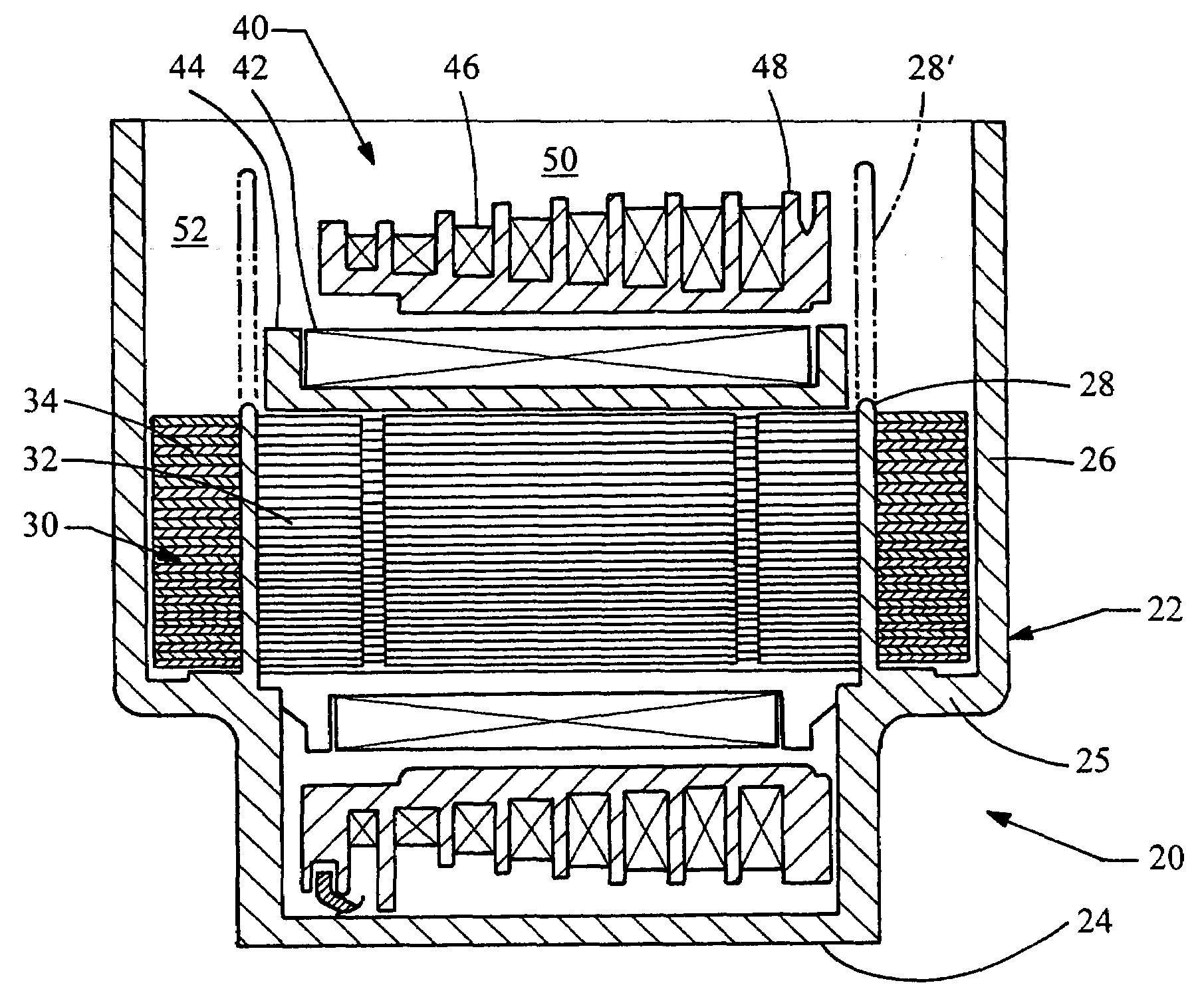
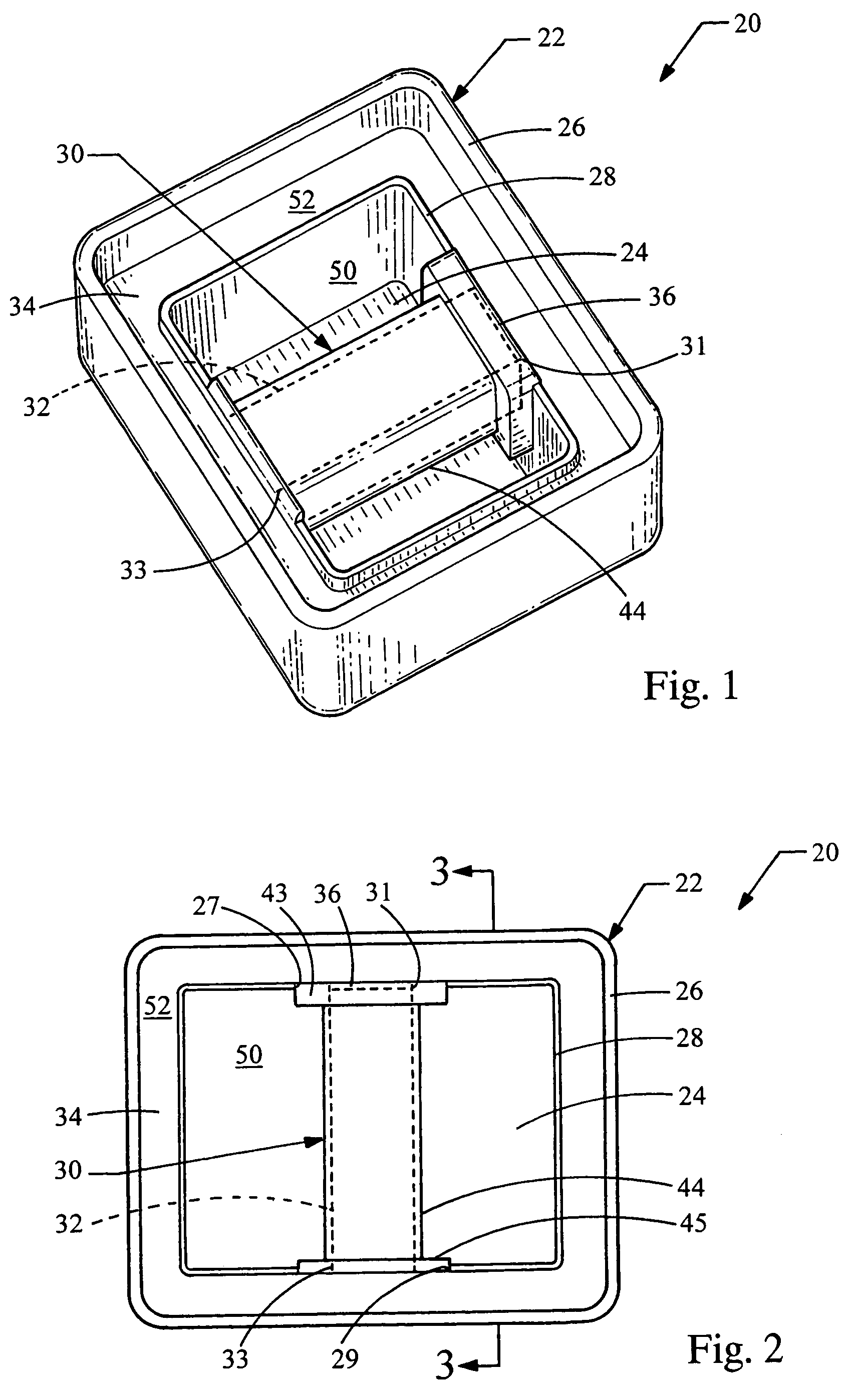
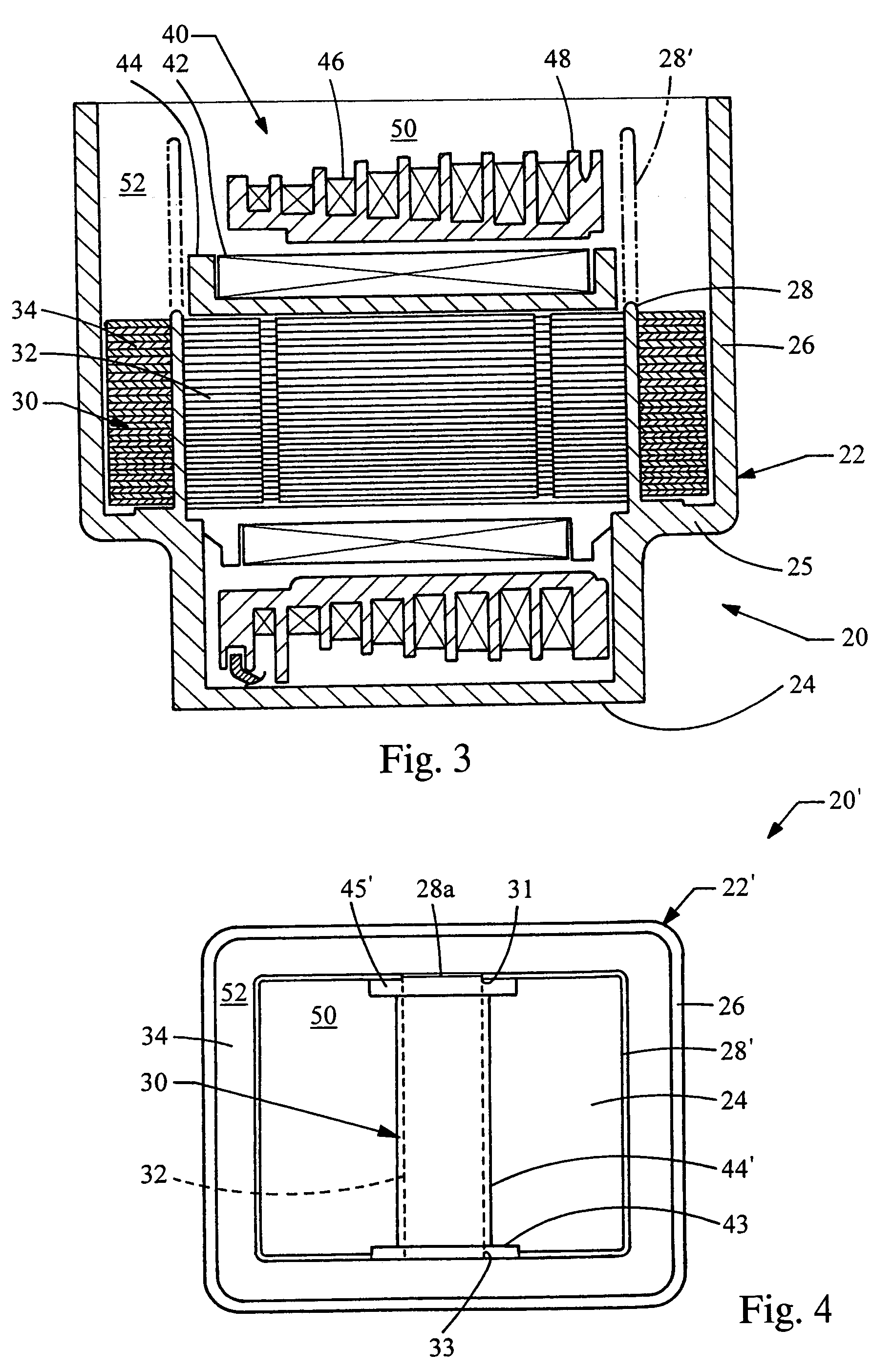
[0016]Turning now to the figures, FIGS. 1, 2 and 3 depict perspective, top and cross-sectional views of an ignition coil 20 constructed in accordance with the teachings of the present invention. The ignition coil 20 generally includes a housing member 22 which encloses a core assembly 30 and a coil assembly 40 (FIG. 3). The housing 22 includes a bottom wall 24 and an outer wall 26 extending upwardly from the bottom wall 24. The outer wall 26 extends around the periphery of the ignition coil 20.

[0017]The housing 22 also includes an inner wall 28 which is spaced radially inwardly from the outer wall 26. As best seen in FIGS. 1 and 2, the inner wall 28 generally defines an inner compartment 50. An outer compartment 52 is defined between the inner wall 28 and the outer 26. As such, the outer compartment 52 is annular or ring-shaped. As will be discussed in more detail below, the inner wall 28 is employed in order to prevent propagation of cracks in an encapsulate filling the housing 22,...


PUM

PropertyMeasurementUnit
ductilityaaaaaaaaaa
thicknessaaaaaaaaaa
magnetic fluxaaaaaaaaaa

Abstract

An ignition coil for an internal combustion engine minimizes the propagation of cracks in the encapsulate material surrounding the components of the ignition coil and provides a supplemental dielectric barrier. In one embodiment, the ignition coil comprises a housing, an outer core, an inner coil, and a coil assembly. The housing includes a bottom wall connected to an outer wall extending around the periphery of the housing. The outer core is positioned inside the outer wall, while the inner core is positioned inside the outer core. The coil assembly includes a primary winding and a secondary winding concentrically positioned relative to each other. The coil assembly is mounted to the inner core and positioned inside the outer core. The housing further includes an inner wall extending along the inner periphery of the outer core and positioned between the outer core and the coil assembly to prevent propagation of cracks.

Description

FIELD OF THE INVENTION[0001]The present invention relates generally to ignitions coils, and more particularly relates to limiting the propagation of cracks in the encapsulate material of the ignition coil.BACKGROUND OF THE INVENTION[0002]Ignition coils typically contain a variety of internal components constructed of a variety of different materials. In general, ignition coils typically contain a core assembly constructed of steel lamination stacks upon which the primary and secondary coils of a coil assembly are mounted. The primary and secondary coils typically include a plastic bobbin which is wound with copper wire. The core assembly includes an outer steel lamination stack that engages an inner lamination stack and extends around the coil assembly. A plastic housing is provided to enclose these aforementioned components. An encapsulate such as a thermosetting resin is poured into the housing to fill all gaps that surround the entire assembly.[0003]The lamination stacks forming ...

Claims


Application Information

Patent Timeline
Patent Type & Authority Patents(United States)
IPC IPC(8): H01F27/02H01F27/26H01F38/12
CPCH01F27/266H01F38/12
Inventor KLOCINSKI, JAMES JOHNBAUMAN, ROBERT CHARLESBURCHETT, RICK S.WALKER, WILLIAM DOUGLAS
Owner FORD GLOBAL TECH LLC
Why Eureka
Try Eureka