Lighting control apparatus with a plurality of lighting devices

a technology of lighting control apparatus and lighting device, which is applied in the direction of color television details, television systems, instruments, etc., can solve the problems of insufficient cooling of leds, insufficient use of post-exposure time, and increased temperature of leds, so as to reduce the accumulation of heat

Inactive Publication Date: 2007-04-24
ASAHI KOGAKU KOGYO KK
View PDF9 Cites 22 Cited by
  • Summary
  • Abstract
  • Description
  • Claims
  • Application Information

AI Technical Summary

Benefits of technology

[0014]Therefore, an object of the present invention is to provide an apparatus that restrains the accumulation of heat caused by the continuous radiation of an LED etc. of a lighting device, during the continuous shot mode or video mode.

Problems solved by technology

However, the temperature of an LED goes up due to continuous radiation of the LED.
However, the above-discussed Japanese unexamined patent publication does not disclose the temperature rise of the LED due to the continuous radiation of the LED in the continuous shot mode.
However, when the length of the post-exposure time is shortened in order to increase the number of frames which can be imaged in a unit of time, the cooling of the LED can not be carried out sufficiently by utilizing the post-exposure time.

Method used


Image

  • Lighting control apparatus with a plurality of lighting devices
  • Lighting control apparatus with a plurality of lighting devices
  • Lighting control apparatus with a plurality of lighting devices

Examples


Embodiment Construction

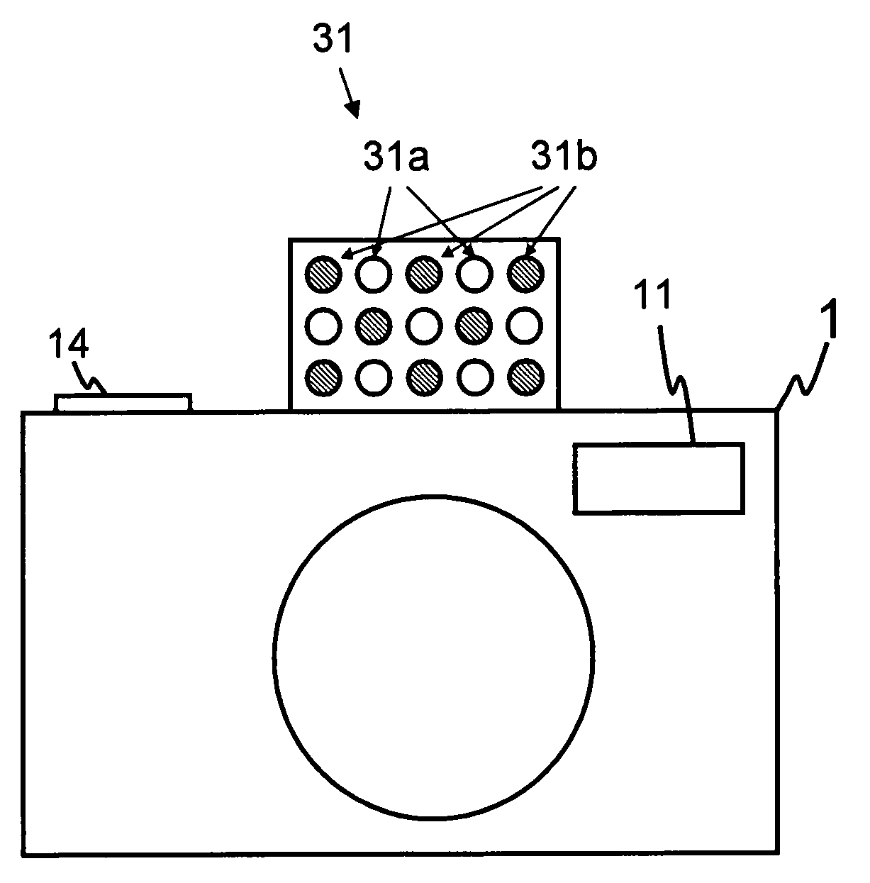
[0030]The present invention is described below with reference to the embodiments shown in the drawings. FIG. 3 shows a perspective view of a photographing apparatus 1 which comprises a lighting control unit of this embodiment, viewed from the back of the photographing apparatus 1. FIG. 4 is a front view of the photographing apparatus 1. FIG. 5 is a circuit construction diagram of the photographing apparatus 1. In this embodiment, the photographing apparatus 1 is a digital camera.

[0031]The photographing apparatus 1 comprises an optical finder 11, an LED on button 12, an LED on switch 12a, a photometric switch 13a, a release button 14, a release switch 14a, a continuous shot button 15, a continuous shot switch 15a, a video button 16, a video switch 16a, an LCD monitor 17, an LED 31 for lighting, and an illuminating circuit 33.

[0032]The photographing apparatus 1 comprises an imaging block 22, an AE (automatic exposure) unit 23, and an AF (automatic focusing) unit 24. The imaging block ...


PUM


Abstract

A lighting control apparatus of a photographing apparatus, comprises a plurality of lighting devices, a continuous imaging control processor, and a pulse-signal generating and control processor. The plurality of lighting devices illuminate a photographic subject by receiving a pulse signal which has a certain cycle in the exposure time. The continuous imaging control processor performs a continuous imaging operation where a plurality of images of the photographic subject are continuously imaged. The pulse-signal generating and controlling processor supplies a pulse signal to each of the lighting devices, cyclically every exposure time, so that one lighting device is illuminated at any given time.

Description

BACKGROUND OF THE INVENTION[0001]1. Field of the Invention[0002]The present invention relates to a lighting control apparatus for a photographing apparatus, and in particular to improvement of the lighting action in the continuous or video mode.[0003]2. Description of the Related Art[0004]A lighting device which uses LEDs is proposed, in place of a lighting device which uses strobe radiation such as a xenon pipe which has been widely used with photographing apparatus, such as a camera. LEDs can be driven at a low voltage, and the circuit construction of the LED is simple.[0005]However, the temperature of an LED goes up due to continuous radiation of the LED. The rise in the LED temperature causes a decrease of the quantity of light emitted by the LED. FIG. 1 shows the relation between the temperature rise and the quantity of light emitted by the LED, so that FIG. 1 shows that the quantity of light, in other words, the brightness of the LED, falls along with the temperature rise of t...

Claims


Application Information

Patent Timeline
Patent Type & Authority Patents(United States)
IPC IPC(8): G03B15/03G03B15/02H04N5/238
CPCG03B15/03H04N5/2256H04N23/56
Inventor UENAKA, YUKIO
Owner ASAHI KOGAKU KOGYO KK
Why Eureka
Try Eureka