Embedded thermal control system for high field MR scanners

a technology of thermal control system and scanner, which is applied in the field of magnetic resonance imaging (mri) systems, can solve the problems of force a halt in operation, higher power dissipation, and higher temperatures in the scanner

Active Publication Date: 2007-04-24
GENERAL ELECTRIC CO
View PDF6 Cites 10 Cited by
  • Summary
  • Abstract
  • Description
  • Claims
  • Application Information

AI Technical Summary

Benefits of technology

The present invention has several benefits including preventing damage from excessive heat caused by energy scanners. It does this by reducing the amount of input power used during operation. This helps to maintain safe operating conditions for the device being tested.

Problems solved by technology

This patent describes how traditional magnetic resonance imaging machines have limitations when trying to achieve better image quality due to temperature restrictions caused by heat generated by the machine's components. The technical problem addressed by this patent is finding ways to increase the allowed peak power in the coil while still controlling the temperature of the entire machine.

Method used


Image

  • Embedded thermal control system for high field MR scanners
  • Embedded thermal control system for high field MR scanners
  • Embedded thermal control system for high field MR scanners

Examples


Embodiment Construction

[0017]In each of the following figures, the same reference numerals are used to refer to the same components. While the present invention is described with respect to a thermal control method and apparatus for high field MR scanners, the present invention may be adapted to set dynamic limits on power received in gradient coils within various systems including: MRI systems, magnetic resonance spectroscopy systems, and other applications where thermal conditions interfere with system functions.

[0018]In the following description, various operating parameters and components are described for one constructed embodiment. These specific parameters and components are included as examples and are not meant to be limiting.

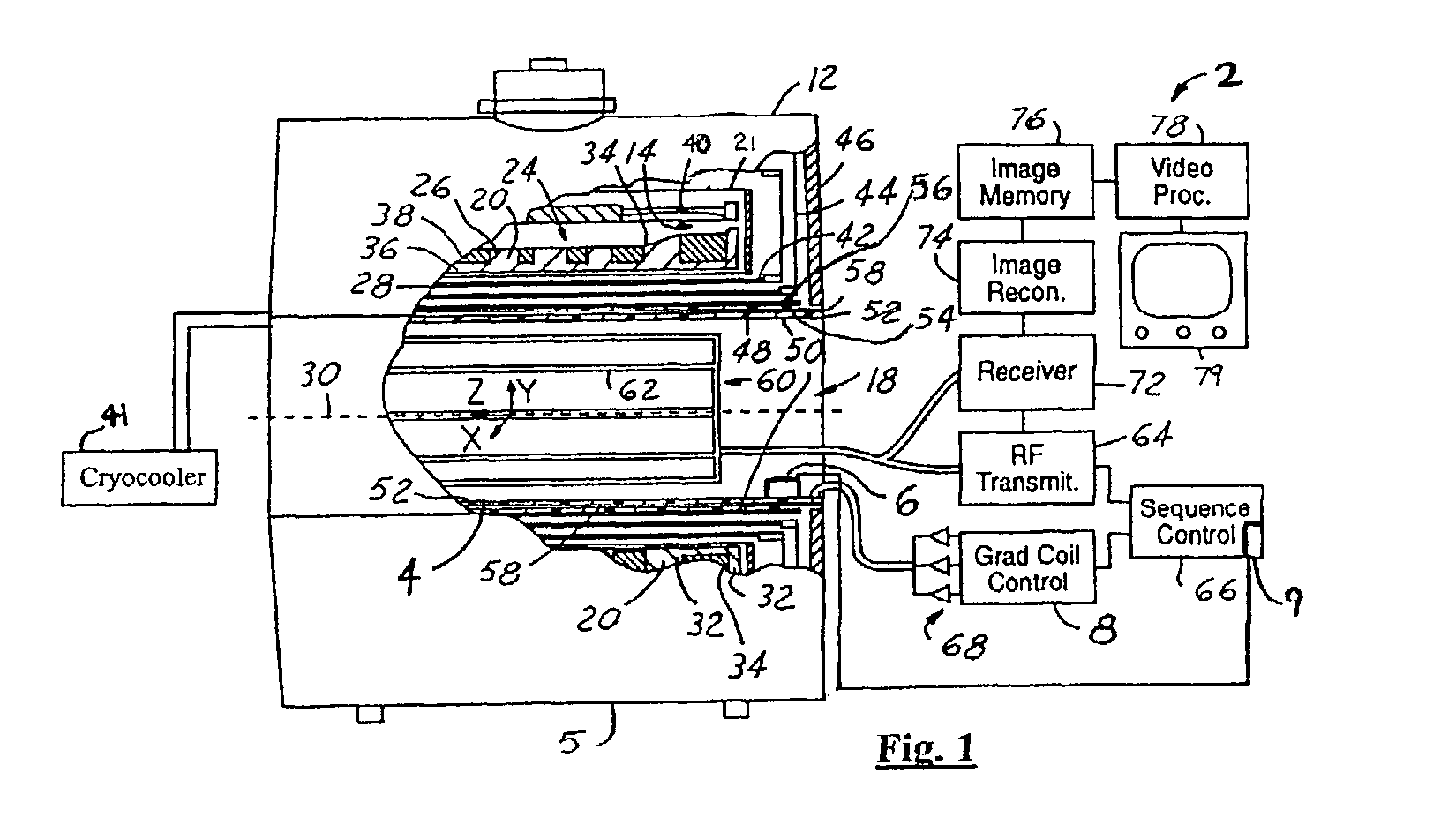
[0019]Also in the following description, a MRI system component may include any one of the following: a superconducting magnet, a superconducting magnet support structure, a gradient magnet assembly, a cryostat, a cryocooler, a cryostat support structure, or any other MRI sy...


PUM


Abstract

A thermal control system having an initial bore condition and a thermal boundary condition for an MRI includes a thermal controller adapted to set at least one dynamic limit on power input into an MRI gradient coil. The dynamic limit is determined for a first commanded prescription as a function of the initial bore condition and the thermal boundary condition.

Description


Claims


Application Information

Patent Timeline
Owner GENERAL ELECTRIC CO
Why Eureka
Try Eureka