Screen frame with integral roll screen compartment and improvements thereof

a technology of screen frame and roll screen compartment, which is applied in the direction of sunshade, curtain suspension device, building components, etc., can solve the problems of unsatisfactory needs, unsatisfactory needs, and inability to meet the needs of homeowners, so as to achieve the effect of reducing the amount of effort and facilitating and simply placing or dropping into position

Inactive Publication Date: 2007-05-01
420820 ONTARIO
View PDF22 Cites 48 Cited by
  • Summary
  • Abstract
  • Description
  • Claims
  • Application Information

AI Technical Summary

Benefits of technology

[0072]In yet another aspect of the invention, the flexible wind retainer previously described does not interfere with the retraction of the screen, said wind retainer including a guide part and having extending there from and perpendicular thereto, two thin flanges which capture the screen cloth and which are secured to said cloth by welding by heat, ultra sound, or the like; said thin flanges being sufficiently thin so as not to prevent the smooth retraction of the screen cloth on the roll tube or to impede the paying out thereof. Preferably the wind retainer is positioned at intervals along each edge of the screen cloth so as to provide further guides of the screen with the handle part. In this way the screen cloth will not go out of round, and will roll up flat when accumulated on the screen tube.
[0073]When the term conventional and or existing hardware, channels, tracks or the like is used in this specification with reference to the various aspects of the invention described above it is implied that such hardware, channels, and tracks are utilized to secure existing planar screens found in windows, doors, patio doors and other closure assemblies whether existing, replacement or original assemblies such as but not limited to tilt and slide windows, casement windows, double hung windows, awning windows, pivoting doors, and patio doors. Further it is intended that the screen assembly of the various embodiments of the invention may be easily and simply placed or dropped into position with a minimum of effort without requiring fastening in position with the exception of rotating or retracting a holding pin or the like or making a tension adjustment to the roller. Conventionally hardware channels and / or tracks or the like are located with the various assemblies discussed above to allow this simple installation. The homeowner can therefore use conventional existing hardware for installation of the various embodiments of the present invention or alternatively if desired can provide replacement hardware which may be of any compatible shape or configuration or which may engage the conventional hardware or alternatively may replace it. Simplicity of replacement or installation is the key for our screen assembly.

Problems solved by technology

But such a construction has difficulty in providing an adequate barrier to insects.
They are unsightly and are also costly and may be beyond the level of skill for a homeowner installation.
This construction improves the barrier against insects but raises other issues.
However, such hidden constructions do require that the window frames be manufactured to required specifications to include a void wherein the roll screen may be inserted.
Most manufacturers do not want to do this because of the cost of moulds and dies.
There is therefore, still an unmet need yet unsatisfied which provides a screen construction which does not require an extensive amount of re-tooling.
Some of the problems experienced with these prior art constructions include, with respect to the roll out doors, that a framing section is provided at the threshold of the assembly.
When the roll out screen is accumulated into the roll tube housing, the threshold remains as an obstacle to block the egress of an individual and particularly for those using wheel chairs, walkers and the like.
People without particular challenges may simply step on the threshold obstacle and disform it to prevent the screen from rolling out and requiring an expensive repair.
Further, such installations require expensive labour for installation and may be quite expensive in comparison to a typical sliding screen door which is not fixed in position.
This requires additional manufacturing time.
However they cannot be used to join adjacent frame sections.
Although the product may be esthetically pleasing once assembled, the threshold obstacle is evident which must be present to provide support for the leading edge of the roll screen as it moves across the opening.
However, a typical known sliding screen frame, for installation adjacent a patio door, when positioned across the patio door opening blocks the occupants view of the yard and may be esthetically displeasing.
If the screen door is slid to the opposite position away from the opening then the opposite glass pane is obstructed as well.
However this construction is cumbersome and bulky and provides no compatible simple braking surfaces separate from the shaft provided with a free wheeling bushing and compatible bracket.
U.S. Pat. No. 5,099,906 teaches the use of a centrifugal clutch based braking device that is mounted on the interior of the roll screen which is complicated to assemble and manufacture.
This particular braking system is ineffective for vertically oriented screen rolls since the braking action forces are parallel to the screen roll itself and would be counteracted by gravity if mounted vertically.
Another cumbersome braking device for a horizontal system is disclosed in U.S. Pat. No. 4,838,333.
There are no means of retaining the edges of the screen cloth in place against the forces generated by the wind blowing on the screen.
If the wind forces are high enough, this can cause release of the screen from the guide channel that can allow insects to pass.
Though solving the problem of securing the motion of the screen at all sides of the framework it poses another problem in that the screen will not properly accumulate on the roll.
Further if the beads do not release from the guide channel the screen cloth may be torn resulting in costly repairs occurring when greater forces than that of the wind such as the force of a pet jumping up against the screen.
The screen should easily release from the guide channel and not be preventing from properly retracting.
This solution is overly complicated and requires gripping surfaces within a guide channel to engage the screen edge.
In spite of the numerous efforts made to provide an acceptable roll screen for windows and doors there still remains a long felt need left unaddressed in the art for a roll screen assembly and improvements thereof which may be simply and easily installed by the homeowner.

Method used


Image

  • Screen frame with integral roll screen compartment and improvements thereof
  • Screen frame with integral roll screen compartment and improvements thereof
  • Screen frame with integral roll screen compartment and improvements thereof

Examples


Embodiment Construction

[0098]Although the following description focuses on a patio door screen, it is not intended that the invention be limited in this aspect. The invention also may be embodied with other doors, windows, or the like. Those skilled in the art will recognize these other uses without limitation.

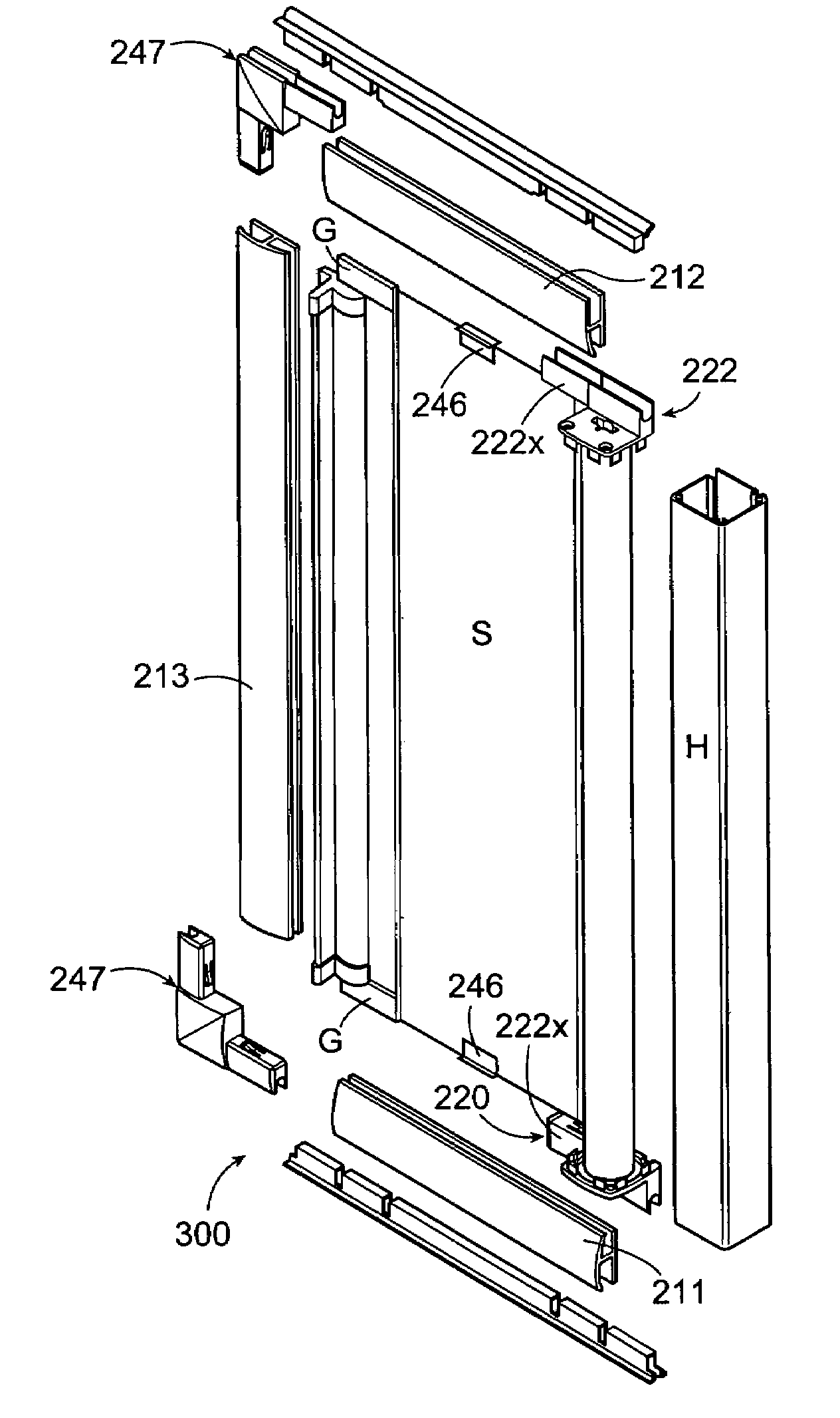
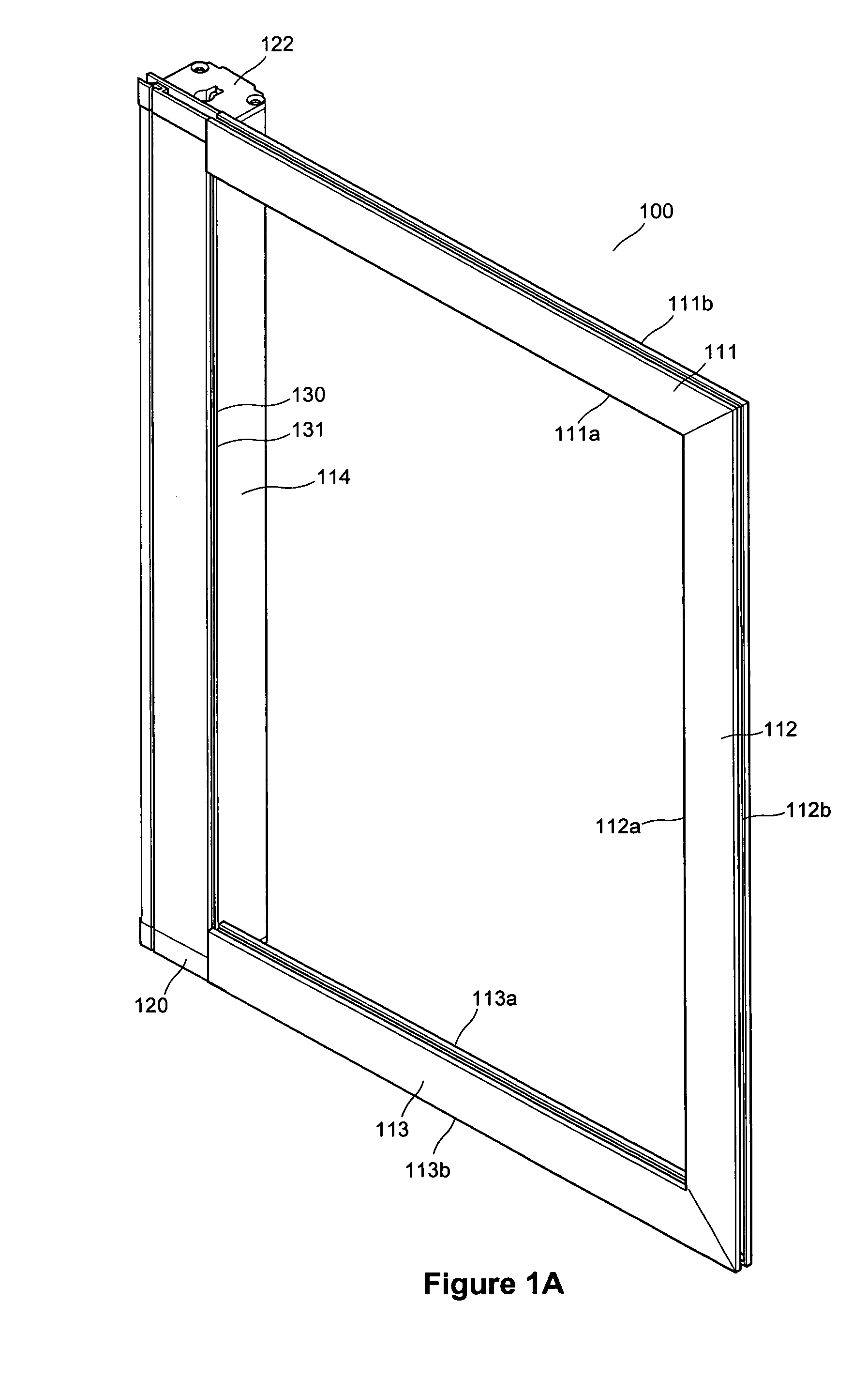
[0099]Referring generally to the figures, there is illustrated a screen frame assembly (10) which includes a screen housing (14) and frame sections (11, 12, and 13) making up the frame (10). The assembly (10) slides within an opening of a closure assembly such as a patio door. The sliding action of the screen frame (10) is accomplished by sliding the screen frame along the edges (11b and 13b) within tracks or channels normally found within a patio door assembly. These channels are found in the sill and the header of the door assembly. The screen frame (10) therefore moves as is known in prior art sliding constructions. However, integral with the framing section (10) is a compartment (15) within whic...


PUM


Abstract

A sliding screen frame for a closure assembly having an opening and an existing track for mounting a screen, the screen frame has framing sections with both inner and outer side edges, and a housing from which a screen is payed out and accumulated. The framing sections are adapted on the outer side edge to interfit with the existing track of the closure assembly to enable the sliding screen frame to slide across the opening of the closure assembly and the frame sections also being adapted on the inner side edge thereof to support and guide the free end of the screen between a fully payed out and a fully accumulated position. The screen frame has a mitreless corner connector for connecting adjacent framing sections without the need for mitre cuts thereof to establish continuity between the corner connector and the adjacent framing sections.

Description

[0001]This is a continuation-in-part of US application Ser. No. 10 / 115,084 filed Apr. 4, 2002, now U.S. Pat. No. 6,701,994 B2.FIELD OF THE INVENTION[0002]This invention relates to improvements to screens for closure assemblies and in a preferred embodiment for patio doors, and windows.BACKGROUND OF THE INVENTION[0003]In the art there exists numerous devices which provide screening to prevent insects from entering open windows and patio doors. These screening devices may be placed in position within a channel provided with the frame sections of typical window or door assemblies with the screen frame of a predetermined thickness so as to easily fit within the channel. Patio door screens may be slideable in a channel on a track assisted by rollers and moveable to and from the position wherein the screen blocks the opening when the door is in the open position and prevents insects from entering the dwelling, to a position away from the opening wherein the screen does not block the openi...

Claims


Application Information

Patent Timeline
Patent Type & Authority Patents(United States)
IPC IPC(8): E06B9/40E06B9/54
CPCE06B9/54E06B2009/543
Inventor GOLDENBERG, SHAULDAVIES, SEANKUPENTHIRARAJAN, SINNATHAMBY
Owner 420820 ONTARIO
Why Eureka
Try Eureka