Two position double injection molding apparatus

a double-position, injection molding technology, applied in the direction of dough shaping, manufacturing tools, applications, etc., can solve the problems of relatively high cycle or production time of the injection molding apparatus of the prior art, the molten material must remain, and the period of time can become quite long

Active Publication Date: 2007-05-01
MOLD MASTERS 2007
View PDF25 Cites 42 Cited by
  • Summary
  • Abstract
  • Description
  • Claims
  • Application Information

AI Technical Summary

Problems solved by technology

In order to properly cool and solidify, however, all of the molten material must remain in the cavity aligned with the nozzle for a relatively lengthy period of time before the injection molding apparatus can be opened.
In the case of overmolding, this period of time can become quite lengthy due to the fact that each material must be sufficiently cooled and solidified before introducing another material.
As a result, the injection molding apparatus has to wait this same amount of time before the cavity can be refilled with new molten material to form a new molded product.
This arrangement causes the injection molding apparatus of the prior art to have relatively high cycle or production times, especially with respect to overmolding devices.
The barrier layer molded within the closure layer, however, does not provide a direct seal between the closure and its respective container or bottle.
These extra steps of cutting and stamping or press-fitting the sealing material, however, increase the time, labor, and cost involved with making the closure.
Adding the inner rim, however, involves using a more complex injection molding apparatus and process, thereby resulting in a more expensive closure.
Moreover, the material used for the closure, and thus its inner rim, typically does not have as good of sealing ability as the sealing material used with the two separate layer closures described above.
The disadvantage of the Ochs et al. apparatus is that the seal liner and shell components are made in the same cavity chamber, one after the other, rather than simultaneously in separate cavity chambers.
As a result of this design, the injection molding cycle or production times are greatly increased, thereby also increasing the time, labor, and cost associated with making closures.

Method used


Image

  • Two position double injection molding apparatus
  • Two position double injection molding apparatus
  • Two position double injection molding apparatus

Examples


Embodiment Construction

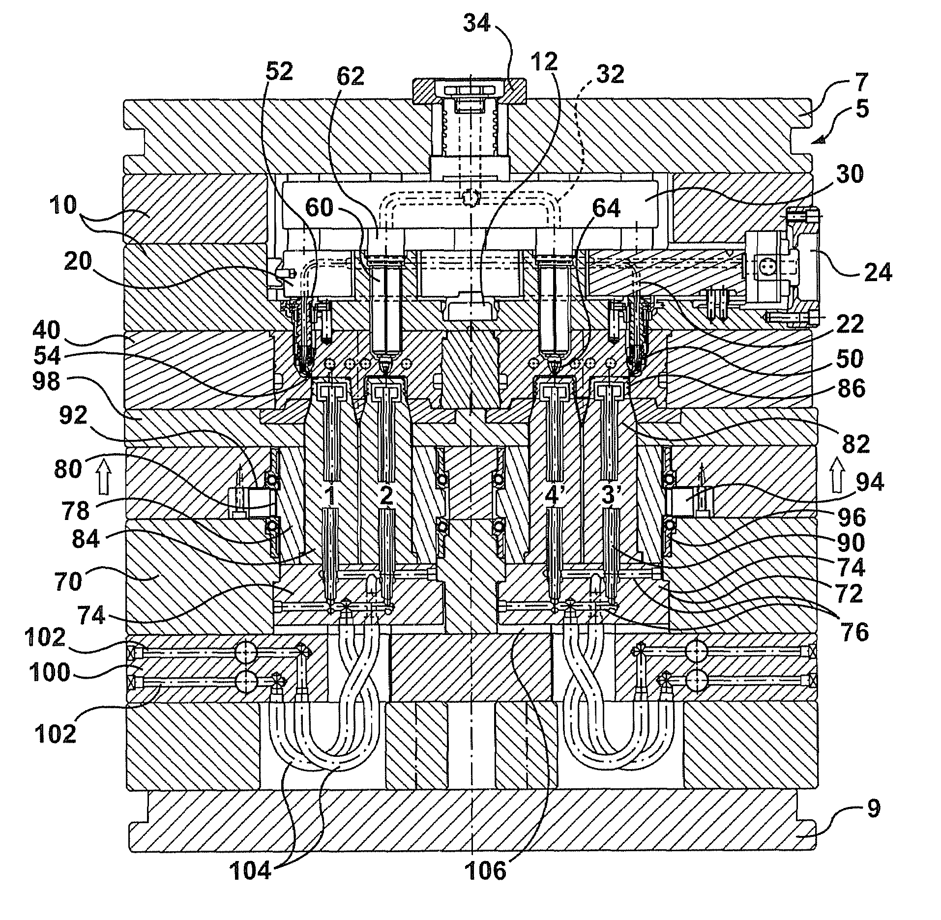
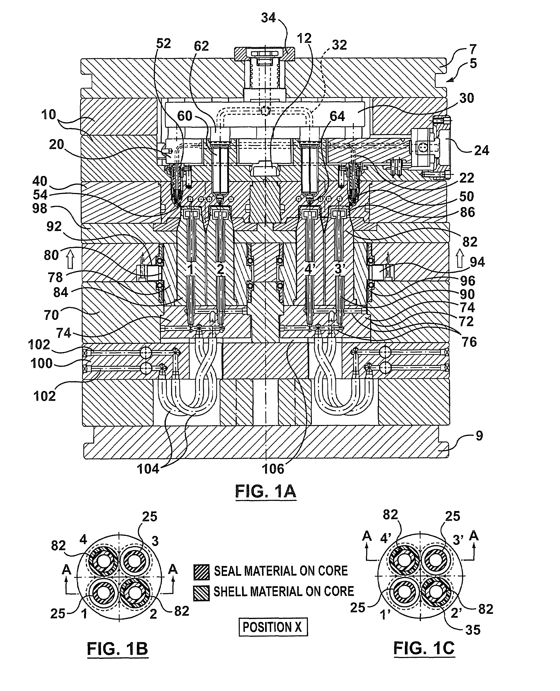
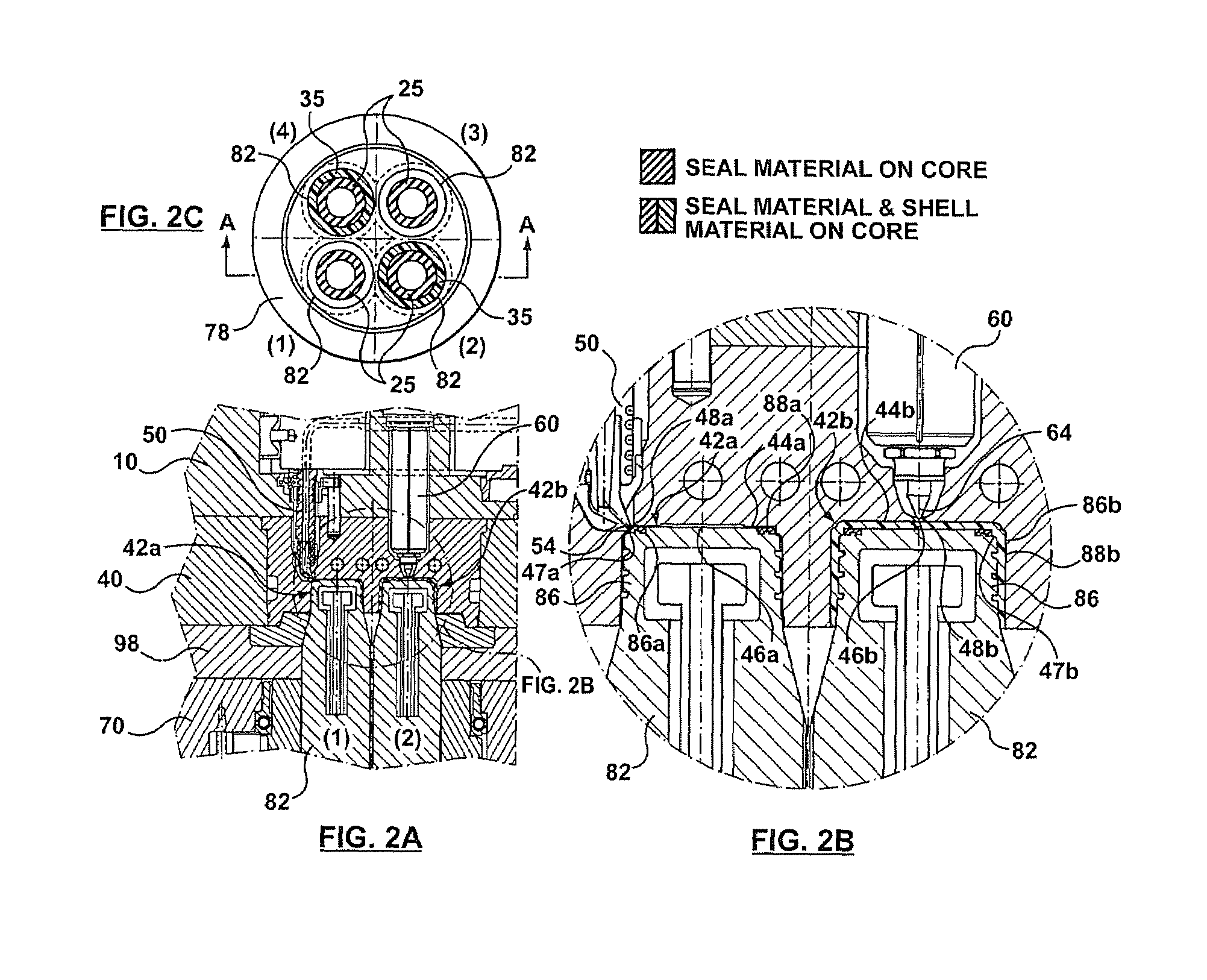
[0027]Turning now to the drawings, FIGS. 1A–1C and 2A–2C show an exemplary embodiment of an injection molding apparatus 5 for molding closures or other products by overmolding with or without sequential and / or simultaneous coinjection. The injection molding apparatus 5 comprises a first clamping plate 7, a second clamping plate 9 spaced from the first clamping plate 7, a manifold plate 10 with a manifold locator 12 positioned between the first and second clamping plates, adjacent to the first clamping plate, a cavity plate 40 positioned between the manifold plate and the second clamping plate, adjacent to the manifold plate, a core plate 70 positioned between the cavity plate and the second clamping plate, a stripper plate 98 positioned between the cavity plate and the core plate, and a support plate 100 positioned between the core plate and the second clamping plate, adjacent to the core plate. It should be understood, however, that the injection molding apparatus 5 may comprise mo...


PUM

PropertyMeasurementUnit
melt distributionaaaaaaaaaa
meltaaaaaaaaaa
timeaaaaaaaaaa

Abstract

An apparatus and method for injection molding of molded products including a first cavity chamber for forming a seal liner, with the first cavity chamber having an outer edge, and a second cavity chamber for forming a shell, with the second cavity chamber having a center and being adjacent to the first cavity chamber. The injection molding apparatus and method also includes a first nozzle for a seal liner material positioned near the outer edge of, and in communication with, the first cavity chamber, and a second nozzle for a shell material positioned near the center of, and in communication with, the second cavity chamber. The injection molding apparatus and method further includes a mold core capable of being positioned in and moved between the first and second cavity chambers.

Description

FIELD OF INVENTION[0001]The present invention relates to a multi-cavity injection molding apparatus and method for making multi-layer, over-molded products. More specifically, it relates to an apparatus and method for two position, double injection molding of closures with integral seal liner and shell components.BACKGROUND OF THE INVENTION[0002]Multi-cavity injection molding apparatus for making single or multi-layer molded container products are well-known. One or more types of molten material are typically injected into a cavity from a nozzle aligned with the center of the cavity to form the molded product. If more than one molten material is used for overmolding (i.e., molding one material over another material), the first material must cool and solidify sufficiently in the cavity before the second material can be injected over the first material. Once all the molten material in the cavity has cooled enough to solidify, the injection molding apparatus is usually opened to eject ...

Claims


Application Information

Patent Timeline
Patent Type & Authority Patents(United States)
IPC IPC(8): B29C45/16
CPCB29C45/1615B29C45/1676B29C45/2681B29C2045/1678B29K2105/253B29L2031/265B29L2031/56B29L2031/565
Inventor LAI, YAT KWONGMATYSEK, PAUL
Owner MOLD MASTERS 2007
Why Eureka
Try Eureka