Radio terminal device antenna and radio terminal device

a radio terminal device and antenna technology, applied in the direction of polarisation/directional diversity, resonant antennas, independent non-interacting antenna combinations, etc., can solve the problems of many devices such as diodes and the like for the control of the current distribution, and it is difficult to produce a small terminal. , to achieve the effect of simple configuration

Active Publication Date: 2007-05-01
PANASONIC CORP
View PDF22 Cites 21 Cited by
  • Summary
  • Abstract
  • Description
  • Claims
  • Application Information

AI Technical Summary

Benefits of technology

[0013]An object of the present invention is to provide an antenna for a radio terminal device and a radio terminal device in which a small-sized product can be realized by configuring with an antenna element that is shorter than 1 wavelength and can be installed at an case, and in which the antenna characteristic can be switched at the same frequency band with a simple component configuration at the same time.

Problems solved by technology

However, in the conventional method as described in JP-A-2001-326514, there were problems in that an antenna element of approximately 1 wavelength was needed, which could not be installed at the case in view of a configuration of an antenna so that it was difficult to produce a small-sized terminal.
Meanwhile, according to the conventional method as described in JP-A-2002-43826, a small-sized antenna could be produced by using a folded loop antenna, but there was a problem in that the balanced characteristic and unbalanced characteristic could not be switched at the same frequency band as they were switched at the phase circuit.
Also, as for the conventional method as described in JP-A-2001-223514, there was a problem in that many devices such as diodes and the like were needed for the control of the current distribution.

Method used


Image

  • Radio terminal device antenna and radio terminal device
  • Radio terminal device antenna and radio terminal device
  • Radio terminal device antenna and radio terminal device

Examples


embodiment 1

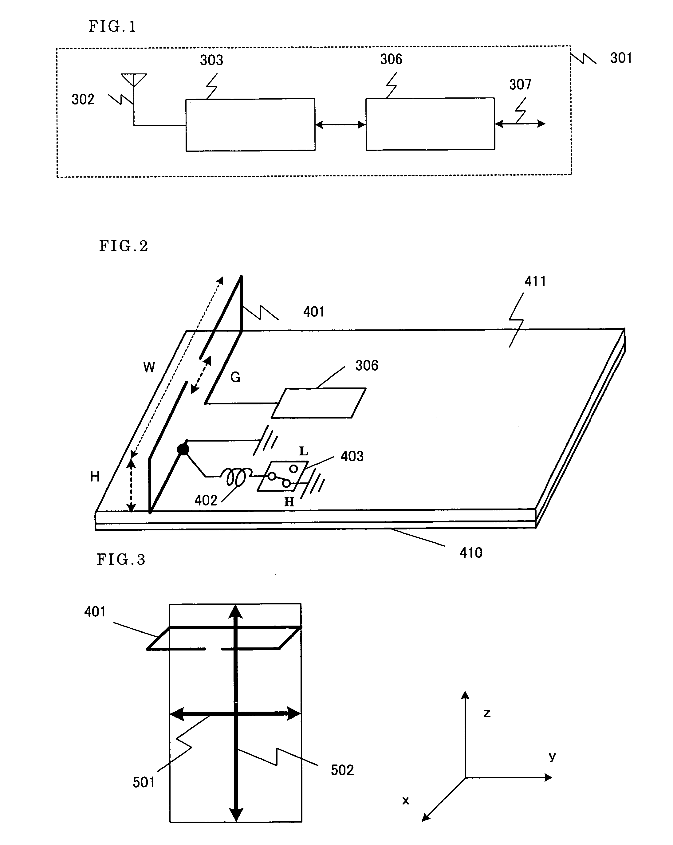
[0063]FIG. 1 shows a configuration of a radio terminal device of the present embodiment.

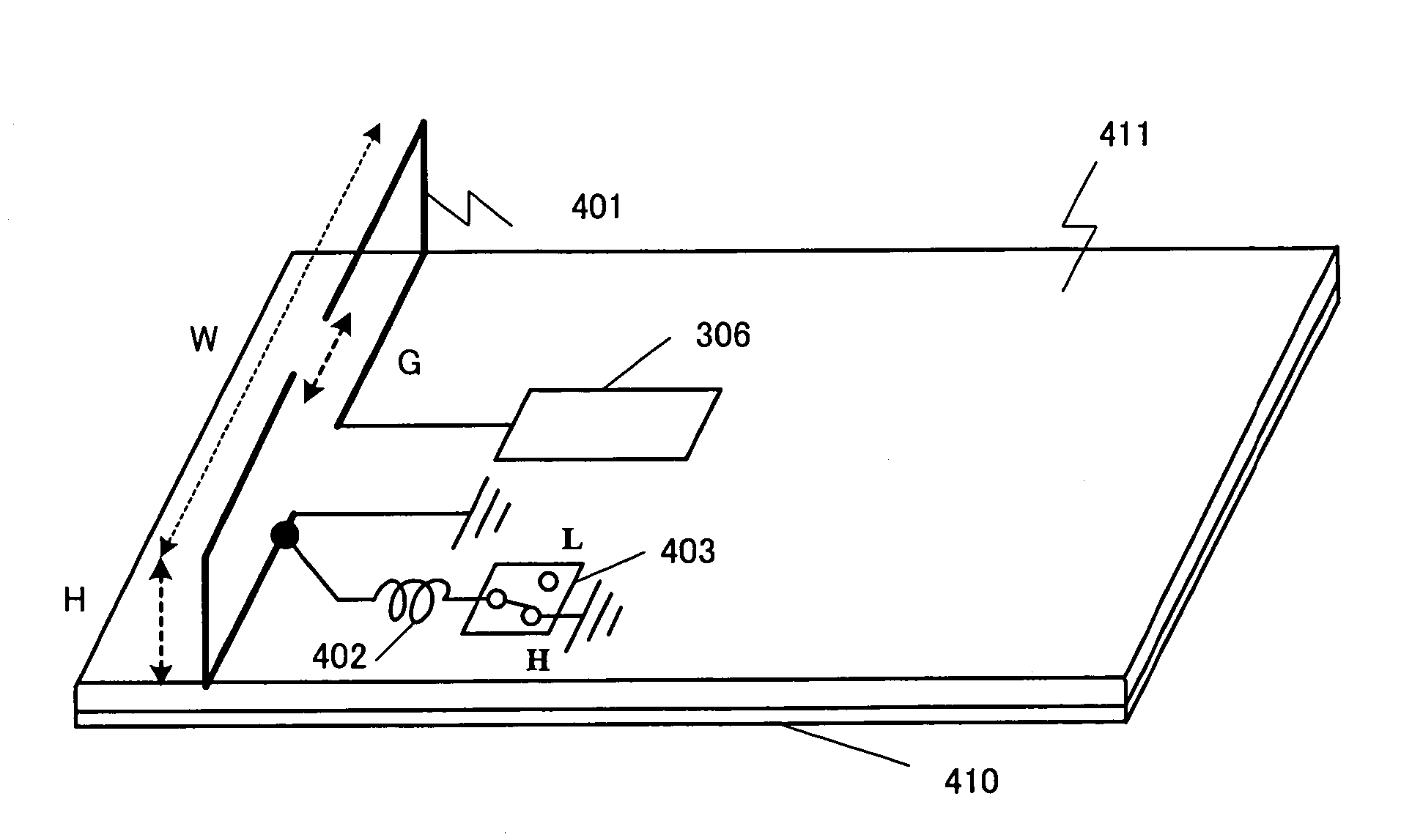
[0064]A radio terminal device 301 has an antenna element 302, an antenna characteristic switching section 303 and a RF circuit section 306. More specific configuration example is shown in FIG. 2.

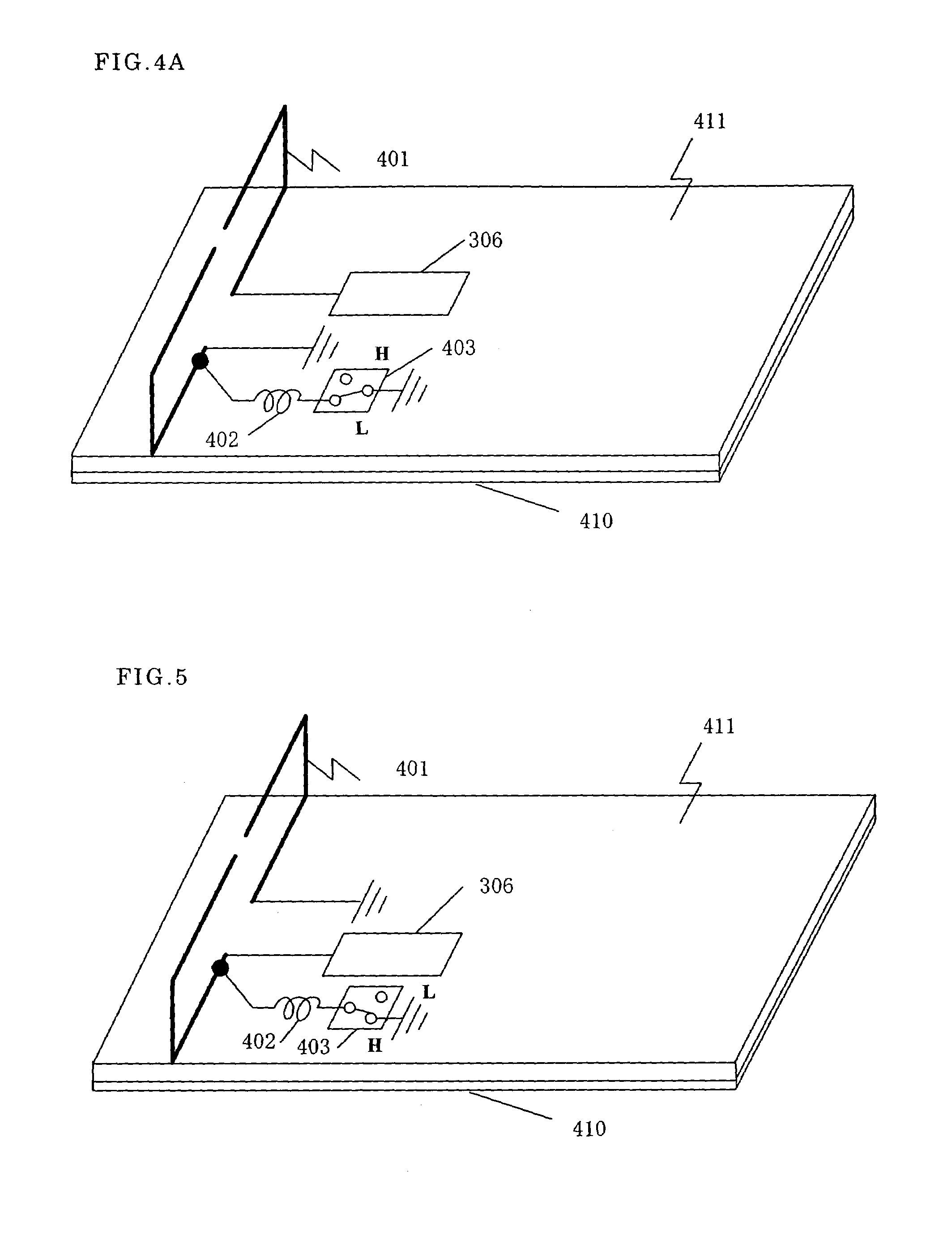
[0065]The antenna element 302 is, for example, a turned-up dipole antenna 401 of about a half wavelength, placed on a substrate 411 in a symmetrical arrangement. The both ends of the turned-up dipole antenna 401 are brought close each other, wherein one end is connected to the RF circuit section 306 and the other end is connected to a conductive substrate 410 which is formed on all over the backside of the substrate 411 through a through-hole. In this configuration, an unbalanced feeding is performed. The conductive substrate 410 in this case corresponds to a conductive substrate.

[0066]The antenna characteristic switching section 303 has a coil 402 and a switch 403. The H terminal of the switch 403 is con...

embodiment 2

[0079]FIG. 17 shows a configuration of the radio terminal device of the present embodiment. This embodiment has a configuration where an operating pattern estimator 304 is further added to the radio terminal device of Embodiment 1. Any other configuration thereof is the same with Embodiment 1.

[0080]This operating pattern estimator 304, in accordance with the usage pattern of the radio terminal device, is to determine the characteristic of the antenna element 302 suitable for the usage pattern thereof, outputting signals to an antenna characteristic switching section 303 for switching the antenna characteristic.

[0081]For example, the operating pattern estimator 304 estimates whether the usage pattern of the radio terminal device is a telephone call mode or data communication mode. This usage pattern estimation is available before communication starts by, for example, detecting whether or not it's a data communication mode (packet communication mode), whether or not there is a voice i...

embodiment 3

[0083]FIG. 11 shows a configuration of the radio terminal device of the present embodiment. This embodiment is different from Embodiment 2 in that a propagation environment estimator 305 is substituted for the operating pattern estimator 304.

[0084]This propagation environment estimator 305, in accordance with the propagation environment, is to determine the characteristic of the antenna element 302 suitable for the propagation environment, thus outputting a signal to an antenna characteristic switching section 303 for switching the antenna characteristic.

[0085]For example, the propagation environment estimator 305 monitors received power, polarization or direction of arrival radio waves and so on.

[0086]FIGS. 12A to 12C show configurations where the direction of an arrival radio wave is monitored. An antenna element 401 can be connected to the propagation environment estimator 305 through switches 1401 and 1402. Because the antenna element 401 can also be recognized as an array anten...


PUM


Abstract

A radio terminal device has an antenna element, a coil, a switch, an RF circuit section and a conductive substrate. The switch is used to switch between a case where current distribution exists only in the antenna element and its vicinities and a case where the current distribution exists not only in the antenna element and its vicinities but also in other places. Additionally, the switch is switched in accordance with the usage pattern in which the user uses the radio terminal device (e.g., telephone call and data communication). This allows the transmission / reception to be performed with the antenna polarization and directivity suitable for the usage pattern. Thus, there can be provided a radio terminal device that exhibits a reception characteristic suitable for a respective situation.

Description

[0001]This application is a U.S. National phase application of PCT International Application PCT / 2003 / 12223.FIELD OF THE INVENTION[0002]The present invention relates to an antenna for a radio terminal device and a radio terminal device.BACKGROUND OF THE INVENTION[0003]In case of the PDC system, as for a conventional antenna for a radio terminal device, a diversity antenna in combination of a whip antenna 102 and a planar inverted F antenna 103, as shown in FIG. 20, has been used well for dealing with a fading problem. However, all of these antennas have the polarization in which the z-axis directional component is big. Therefore, in a radio communications system transmission / reception in the vertical polarization at the base station, when a portable phone is used for telephone call and data communications as shown in FIG. 21, the polarization loss becomes small at the time of data communications as the polarization is the same vertical polarization, while the polarization loss becom...

Claims


Application Information

Patent Timeline
Patent Type & Authority Patents(United States)
IPC IPC(8): H01Q1/24H01Q3/24H01Q1/50H01Q7/00H01Q9/14H01Q9/26H01Q9/42H01Q21/28H04B7/10H04B7/26
CPCH01Q1/243H01Q3/247H01Q7/00H01Q9/26H01Q9/42H01Q21/28
Inventor MIYANO, KENTARONAKAGAWA, YOICHIMIMURA, MASAHIROKOYANAGI, YOSHIOFUJIMOTO, KYOHEI
Owner PANASONIC CORP
Why Eureka
Try Eureka