Rotating-polarization reflector-backed RFID loop antenna apparatus and method

a technology of rotating polarization reflectors and antennas, applied in the direction of antennas, antenna details, electrical devices, etc., can solve the problems of increasing complexity and cost, requiring additional cost and size,

Active Publication Date: 2013-05-09
SYMBOL TECH LLC
View PDF2 Cites 15 Cited by
  • Summary
  • Abstract
  • Description
  • Claims
  • Application Information

AI Technical Summary

Problems solved by technology

Additionally, a phased antenna array could also be used in the RFID reader, but such a solution requires electronic beam steering, adding complexity and cost.
Alternatively, a chandelier ant

Method used


Image

  • Rotating-polarization reflector-backed RFID loop antenna apparatus and method
  • Rotating-polarization reflector-backed RFID loop antenna apparatus and method
  • Rotating-polarization reflector-backed RFID loop antenna apparatus and method

Examples


Embodiment Construction

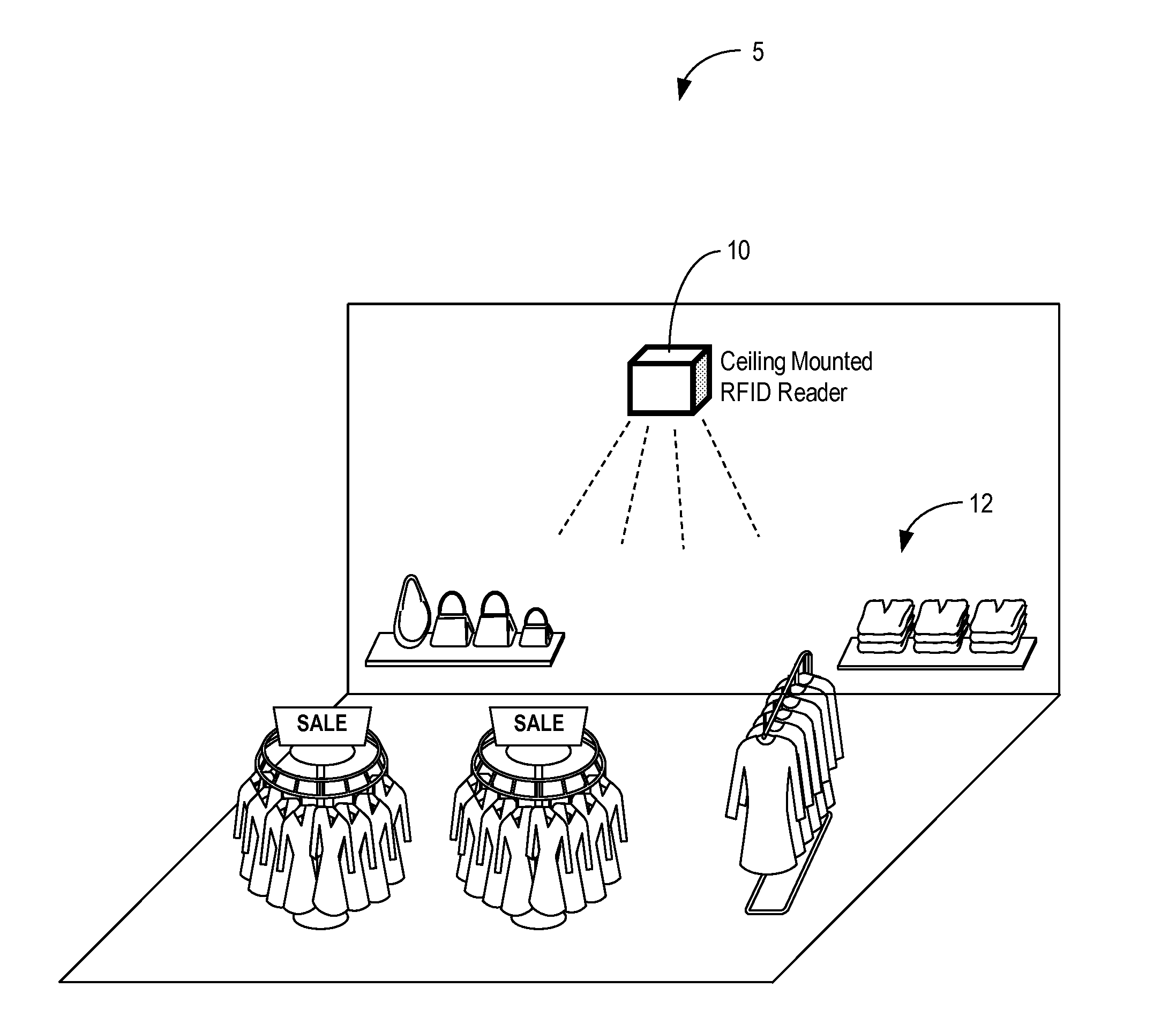
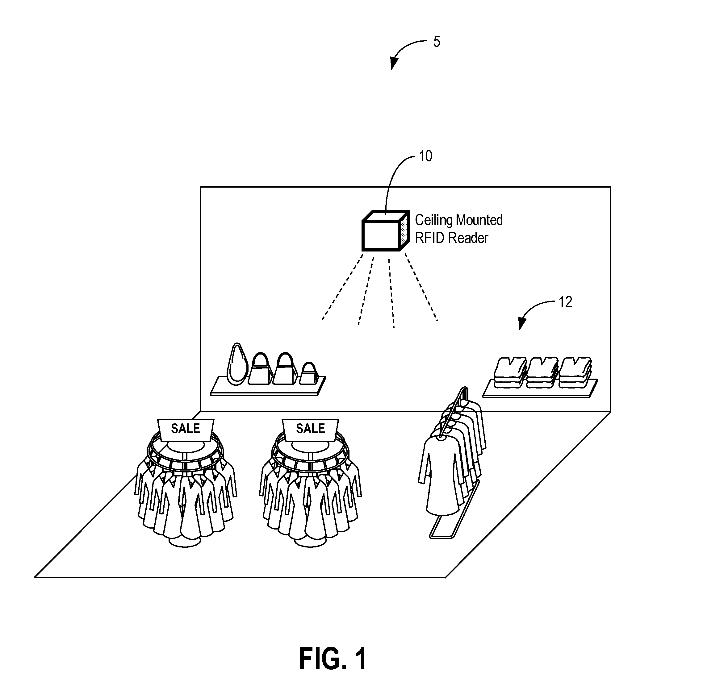
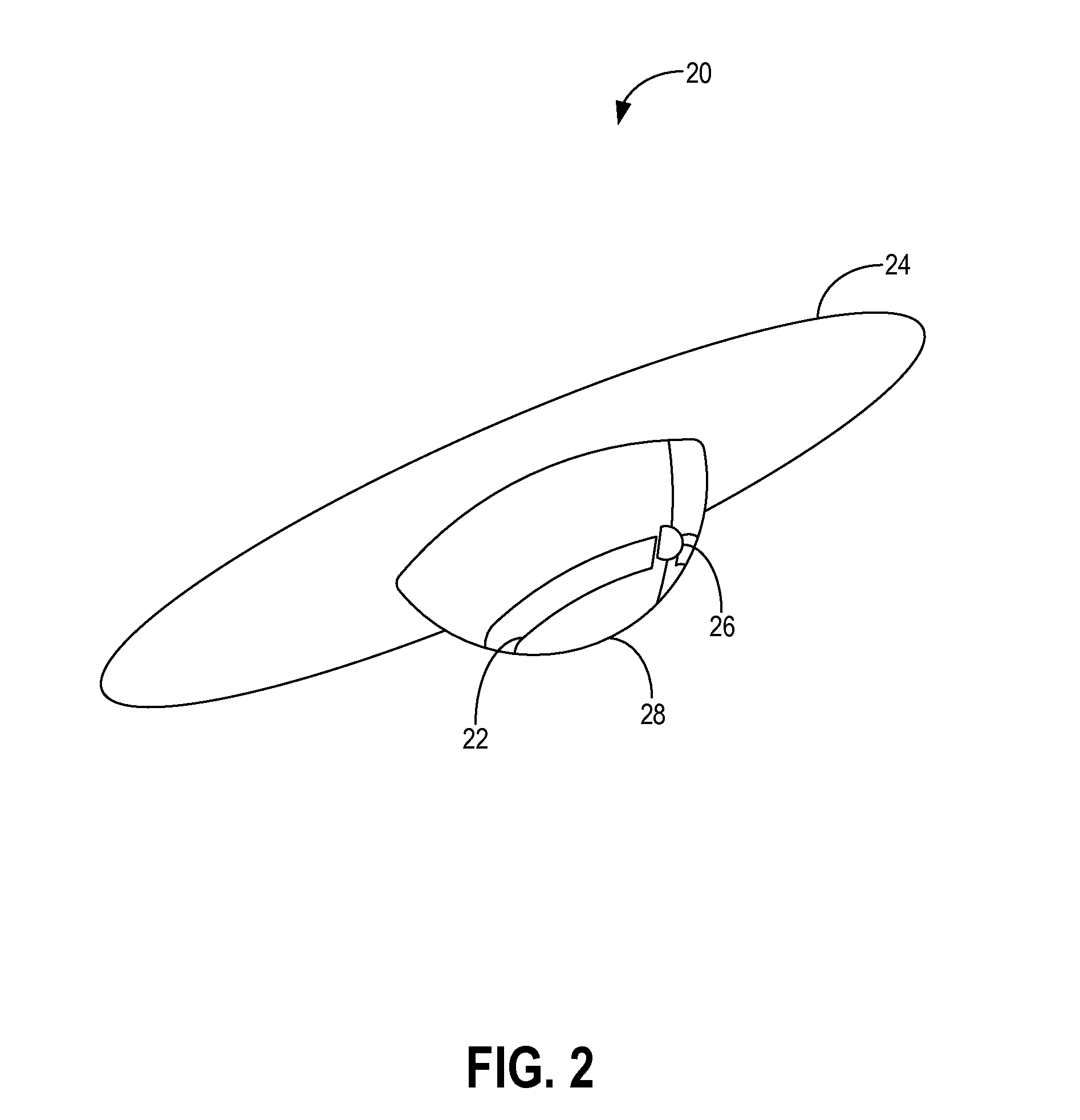
[0018]In various exemplary embodiments, the present disclosure provides a rotating-polarization reflector-backed Radio Frequency Identification (RFID) loop antenna apparatus and method. Advantageously, the loop antenna apparatus and method provides high gain (i.e., maximizing read distances at lowest power), directionality (i.e., ability to focus on specific areas), orientation insensitivity (i.e., (i.e., ability to read RFID tags in any direction or orientation) while occupying minimal volume in overhead configurations.

[0019]In an exemplary embodiment, an antenna apparatus includes a rotatable loop element with a feed and a reflector backing the loop element and configured to reflect radio frequency energy from the loop element in a direction substantially perpendicular to the reflector. The rotatable loop element and the reflector cooperatively form a rotating-polarization reflector-backed loop antenna with directionality responsive to a position and / or orientation of the reflecto...


PUM


Abstract

The present disclosure provides a rotating-polarization reflector-backed Radio Frequency Identification (RFID) loop antenna apparatus and method. The loop antenna apparatus and method provides high gain (i.e., maximizing read distances at lowest power), directionality (i.e., ability to focus on specific areas), orientation insensitivity (i.e., ability to read RFID tags in any direction or orientation) while occupying minimal volume in overhead configurations. In an exemplary embodiment, the loop antenna apparatus includes a reflector and a loop element with the reflector configured to reflect downward RF energy from the loop element. Antenna polarization is controlled by a feed location on the loop element and antenna pattern is controlled by the reflector. Thus, orientation insensitivity may be achieved without changing the antenna pattern by rotating the feed location and not the reflector.

Description

FIELD OF THE DISCLOSURE[0001]The present disclosure relates generally to wireless antennas and more particularly to a rotating-polarization reflector-backed Radio Frequency Identification (RFID) loop antenna apparatus and method.BACKGROUND[0002]Radio Frequency Identification (RFID) is utilized in a variety of applications with RFID readers communicating with RFID tags for purposes of identification, location, tracking, and the like. In an exemplary RFID application, an RFID reader may be mounted overhead (e.g., ceiling mounted) relative to a plurality of RFID tags. For example, in a retail, warehouse, etc. scenario, the RFID reader may be mounted above the RFID tags and their associated objects. Conventional antenna designs may be utilized in overhead configurations but with disadvantages. For example, a Yagi antenna may be utilized in the RFID reader but requires a certain amount of length hanging down from the overhead location. Additionally, a phased antenna array could also be u...

Claims


Application Information

Patent Timeline
IPC IPC(8): H01Q3/00
CPCH01Q1/2216H01Q21/245H01Q19/104H01Q7/00
Inventor BELLOWS, DAVID E.
Owner SYMBOL TECH LLC
Why Eureka
Try Eureka