Integrated cooling system for electronic devices

a cooling system and electronic device technology, applied in the field of electronic devices, can solve the problems of limited heat removal, large waste heat generation of electronic components and assemblies, and particularly severe problems for electronic applications that disperse, and achieve the effect of enhancing heat transfer

Active Publication Date: 2007-05-08
DELPHI TECH IP LTD
View PDF9 Cites 79 Cited by
  • Summary
  • Abstract
  • Description
  • Claims
  • Application Information

AI Technical Summary

Problems solved by technology

Electronic components and assemblies can generate large amounts of waste heat during operation.
If this heat cannot be efficiently removed the temperatures of the electronic components and assemblies can rise to levels that prevent their normal function and can also cause failure.
This issue is particularly severe for electronic applications that dissipate high levels of waste heat or operate in high temperature ambient conditions.
However, the amount of heat that can be removed is limited by the intrinsic thermal conductivity of the materials used and the amount of area in the material available to remove the heat.
These limitations become even more important when the size of the component and assembly becomes smaller and as the density of heat generated at both the component and assembly level increases.
In many electronic applications, this temperature difference is too low to allow for efficient transfer of heat energy away from the heat generating components.
The biggest issue with all of these systems is the need for the containment of the vaporized fluid over the life of the product.
This can result in high packaging cost of these systems.
Because most of these cooling concepts use relatively small amounts of fluid, in high heat applications “dry out” may happen when all of the fluid available is vaporized.
When this happens, the system is no longer capable of removing heat from the electronic component or assembly, potentially causing system failure.
However, due to low specific heat properties of gases when large amounts of heat or high heat densities are an issue, liquid cooling is much more capable of meeting the cooling requirements.
The fabrication and assembly of these individual components can be costly and relatively complicated.
In addition, the interfaces between the various components are subject to leaking which will cause failure of the cooling system.

Method used


Image

  • Integrated cooling system for electronic devices
  • Integrated cooling system for electronic devices
  • Integrated cooling system for electronic devices

Examples


Embodiment Construction

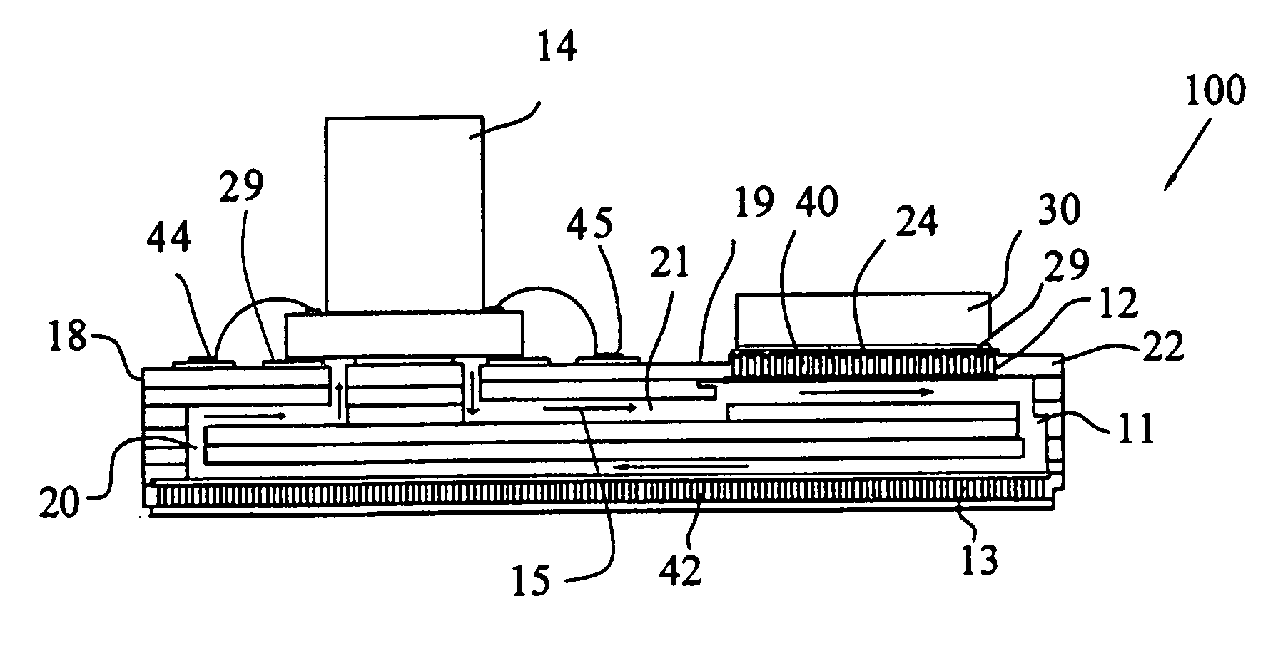
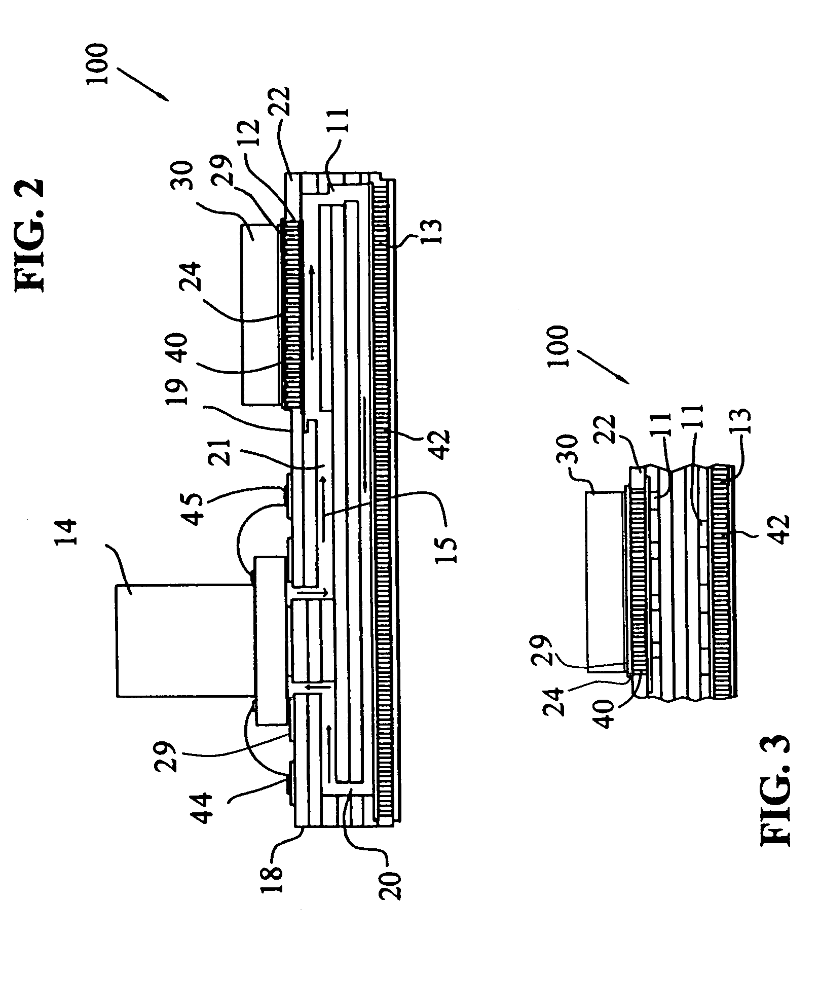
[0050]The present invention provides an integrated electronic cooling system having one or more cooling system components integrated on or within a base or substrate layer(s) during the assembly of the electronic device.

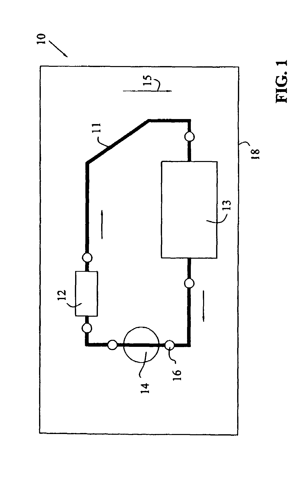
[0051]Referring now to FIG. 1, a system diagram of cooling system 10 of the present invention is illustrated. Cooling system 10 includes cooling system components interconnecting to one another. These components include fluid channel 11 for communicating a cooling fluid, first heat exchanger 12 for transferring heat from a heat generating source to the cooling fluid, second heat exchanger 13 for transferring heat from the hot fluid outside the electronic assembly. As shown, pump 14 is provided to direct the flow of the cooling fluid in the direction indicated by arrow 15 from first heat exchanger 12 to second heat exchanger 13 and re-circulate back to pump 14 and first heat exchanger 12. Also shown is a plurality of ports 16 connected to fluid channel 11 for receivin...


PUM


Abstract

The present invention provides a method for producing an electronic assembly and an electronic assembly with an integrated cooling system for dissipating heat. The electronic assembly comprises a base; and at least one electrical component attached to the base. The base defines an integrated cooling system having a fluid channel spanning within the base and at least one heat exchanger in heat communication with the fluid channel. The integrated cooling system may further include a pump attached to the base for directing the flow of the fluid within the fluid channel, and a port in fluid communication with the fluid channel for receiving fluid from an external source.

Description

TECHNICAL BACKGROUND[0001]1. Field of the Invention[0002]The present invention relates to electronic devices, particularly methods for integrating fluid cooling systems on electronic devices.[0003]2. Description of the Related Art[0004]Electronic components and assemblies can generate large amounts of waste heat during operation. If this heat cannot be efficiently removed the temperatures of the electronic components and assemblies can rise to levels that prevent their normal function and can also cause failure. This issue is particularly severe for electronic applications that dissipate high levels of waste heat or operate in high temperature ambient conditions.[0005]Current solutions may involve removing heat by using one of four heat removal mechanisms or a combination of the four mechanisms. These mechanisms include conduction, convection, radiation, and evaporation.[0006]Conduction is the property of materials to conduct heat energy from hot to colder locations. This is a low c...

Claims


Application Information

Patent Timeline
Patent Type & Authority Patents(United States)
IPC IPC(8): H05K7/20
CPCH05K1/0272H05K7/20254H05K1/0206H05K3/4611H05K2201/064
Inventor CHANG, SHIH-CHIAMYERS, BRUCE A.PEUGH, DARREL E.BERLIN, CARL W.FAIRCHILD, M. RAY
Owner DELPHI TECH IP LTD
Why Eureka
Try Eureka