Self-curling sleeve

a self-curling, sleeve technology, applied in the field of sleeves, can solve the problems of biasing, add to the cost and time required to produce the sleeves,

Active Publication Date: 2007-05-15
FEDERAL MOGUL WORLD WIDE LLC
View PDF20 Cites 64 Cited by
  • Summary
  • Abstract
  • Description
  • Claims
  • Application Information

AI Technical Summary

Problems solved by technology

A significant disadvantage associated with sleeves that are biased into a tubular shape is that the biasing is effected by a separate step in the process of making the sleeve.
The filaments comprising the sleeve may be biased by cold working before weaving or may be biased after weaving by heating the substrate when wrapped about a mandrel, but these actions constitute a separate step that adds to the cost and the time required to produce the sleeve.

Method used


Image

  • Self-curling sleeve
  • Self-curling sleeve
  • Self-curling sleeve

Examples


Embodiment Construction

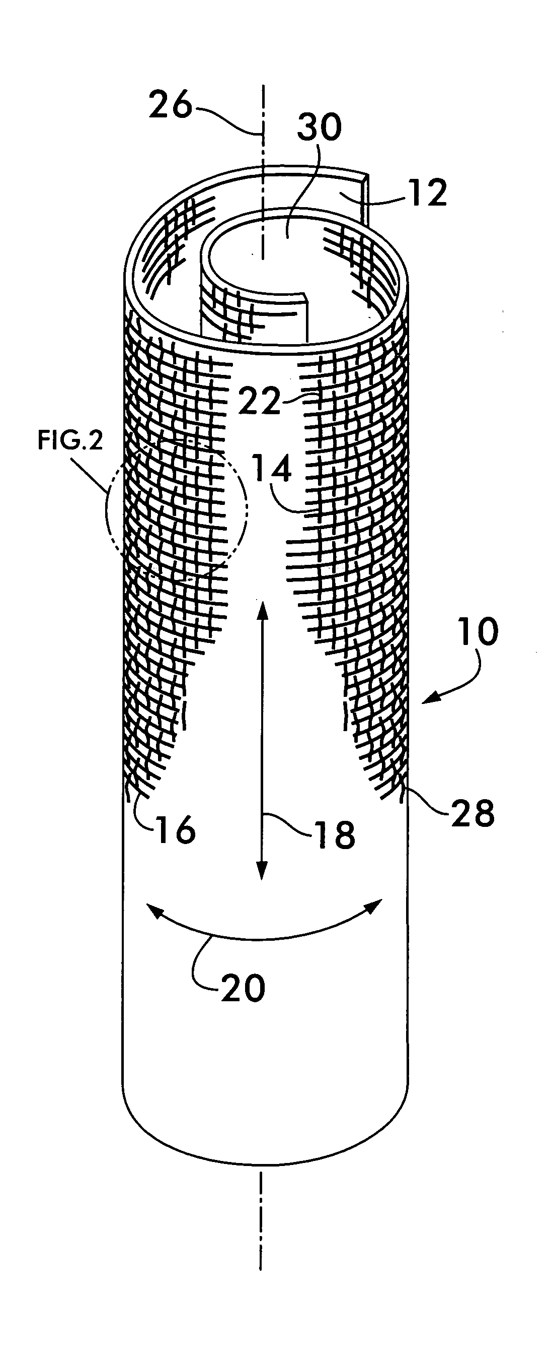
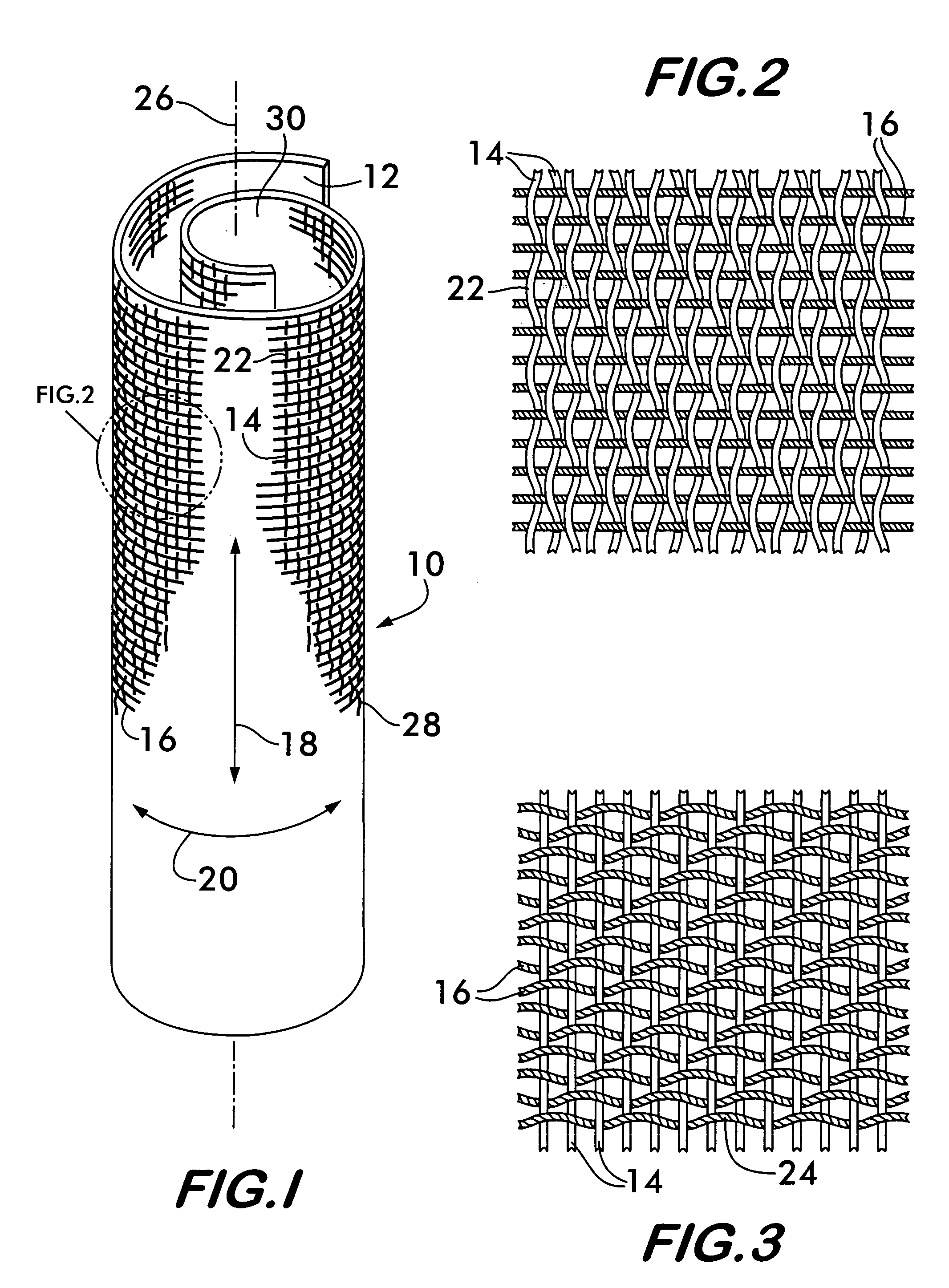
[0018]FIG. 1 shows a self-curling sleeve 10 according to the invention. Sleeve 10 comprises a substrate 12 woven from a plurality of monofilaments 14 and multifilament yarns 16. The monofilaments 14 are oriented in a first direction, shown by arrow 18, and the multifilament yarns 16 are oriented in a second direction, substantially perpendicular to the first direction, and indicated by arrow 20. Preferably, the monofilaments 14 are oriented in the warp direction of the substrate and the multifilament yarns are oriented in the weft direction and constitute the “fill yarns” or “picks” of the weave.

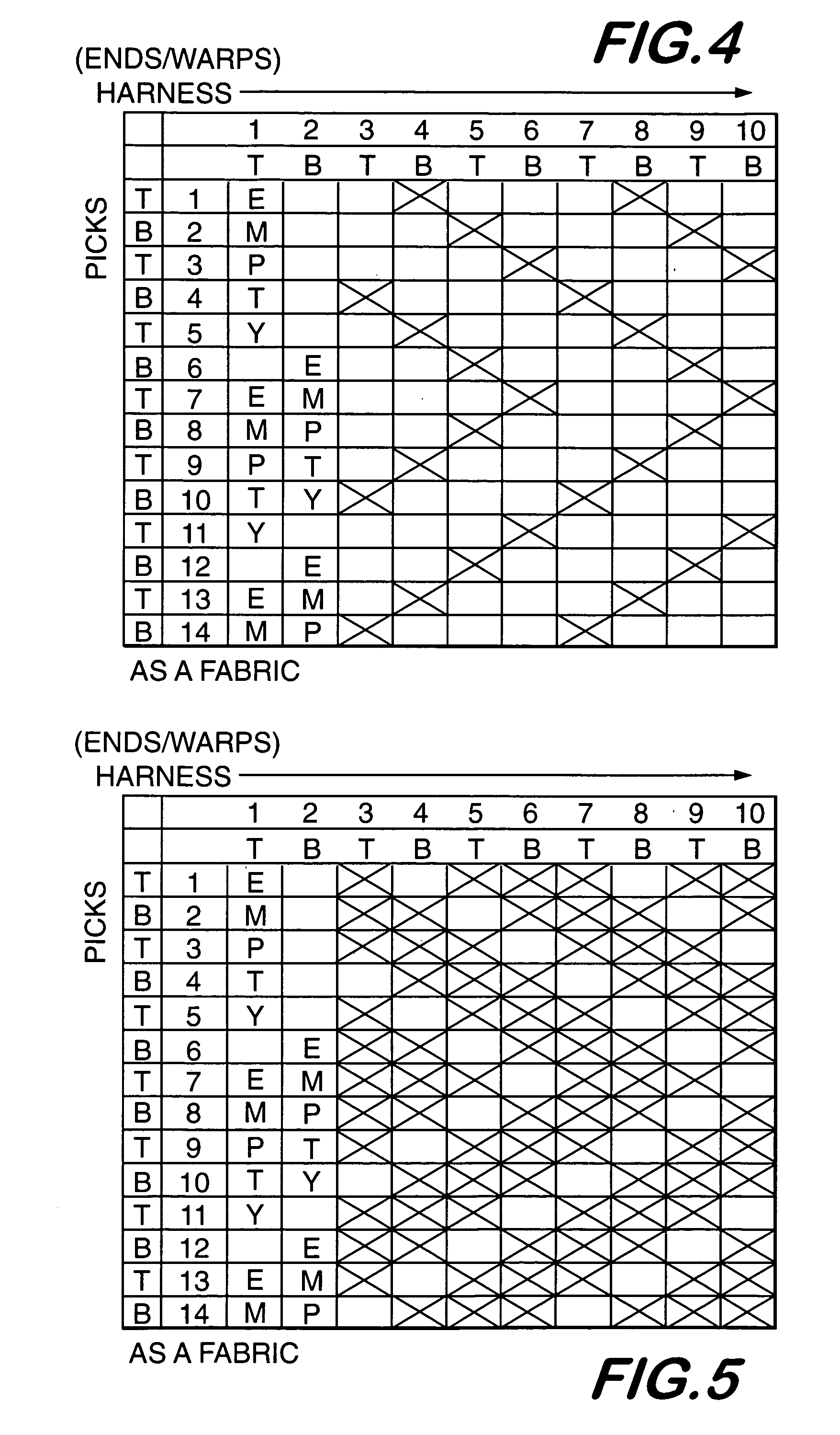
[0019]Preferred weave patterns for weaving the substrate 12 are those such as twills and satin weaves that form “floats” predominantly on one side of the substrate. As shown in FIG. 2, a “float”22 is formed when a filament or yarn, such as monofilament 14, crosses over more than one filament or yarn oriented perpendicular to it, such as weft yarns 16. The substrate is called “warp faced” whe...


PUM

PropertyMeasurementUnit
diametersaaaaaaaaaa
diameteraaaaaaaaaa
diameteraaaaaaaaaa

Abstract

A substrate including a plurality of monofilaments, or a combination of monofilaments and multi-filament yarns oriented in perpendicular directions, has a tendency to curl around a central space. When all monofilaments are used, the monofilaments along one direction may have a larger diameter than the monofilaments along the other direction. The monofilaments are woven such that the larger diameter monofilaments form floats predominantly on one side of the substrate. For the monofilament-multifilament combination the monofilaments form floats predominantly on one side of the substrate. The substrate curls about an axis parallel to the monofilaments forming the floats. The side having the floats faces outwardly away from the central space. Preferably, the monofilaments are oriented in the warp direction along the substrate. The filaments may be woven in a herringbone twill weave, a double cloth herringbone twill weave or a satin weave to provide the floats.

Description

CROSS-REFERENCE TO RELATED APPLICATIONS[0001]This application claims the benefit of U.S. Provisional Patent Application Nos. 60 / 589,270, filed Jul. 20, 2004, and 60 / 657,847, filed Mar. 2, 2005, the entire disclosures of both of which are hereby incorporated herein by reference.FIELD OF THE INVENTION[0002]This invention concerns sleeves for receiving and protecting elongated items, such as wiring harnesses.BACKGROUND OF THE INVENTION[0003]Protective sleeving is used throughout the automotive, marine and aerospace industries to organize and protect elongated items, such as wiring harnesses and optical fiber cables. The sleeving surrounds the elongated items and protects them against cuts, abrasion, radiant heat, vibration induced wear and other harsh environmental threats. When positioned within protective sleeving, the wiring or cables are also held together in a neat bundle, allowing a multiplicity of different items to be handled like a sub-assembly, thus saving time and effort dur...

Claims


Application Information

Patent Timeline
Patent Type & Authority Patents(United States)
IPC IPC(8): D03D3/00D03D15/04D03D3/02D03D15/02D03D3/08D03D15/56D03D15/567
CPCD03D3/08D03D13/004D03D17/00F16L57/06F16L59/10H02G3/0462H02G15/18D03D1/0043D03D23/00
Inventor BAER, ANGELA L.
Owner FEDERAL MOGUL WORLD WIDE LLC
Why Eureka
Try Eureka