Spinal fixation system and related methods

Inactive Publication Date: 2007-05-22
WARSAW ORTHOPEDIC INC
View PDF38 Cites 173 Cited by
  • Summary
  • Abstract
  • Description
  • Claims
  • Application Information

AI Technical Summary

Benefits of technology

[0007]The invention involves apparatus and method for minimizing the height of profile of spinal implants employed for correcting and stabilizing the position of vertebral segments within a patient's spine. Fasteners are secured in two columns, one on each side of the center of the spine. Cross members are connected to the fasteners and support a spinal rod in space provided by removal of portions of spinous processes involved in the treatment of the patient. In some embodiments, the spinal rod is a one-piece item, and

Problems solved by technology

Unfortunately, when the above prior art systems are inserted in a patient, the pedicle screws are typically positioned such that the head of each pedicle screw angles outward away from the center of the spine (i.e., in a lateral orientation).
Because of this screw angle and the fact that the support rods are mounted at about the same height as the pedicle screw heads, there is a significant amount of trauma to the back muscles when this system is installed.
This, in turn, leads to a significant amount of pain after the surgery as well as a long

Method used


Image

  • Spinal fixation system and related methods
  • Spinal fixation system and related methods
  • Spinal fixation system and related methods

Examples


Embodiment Construction

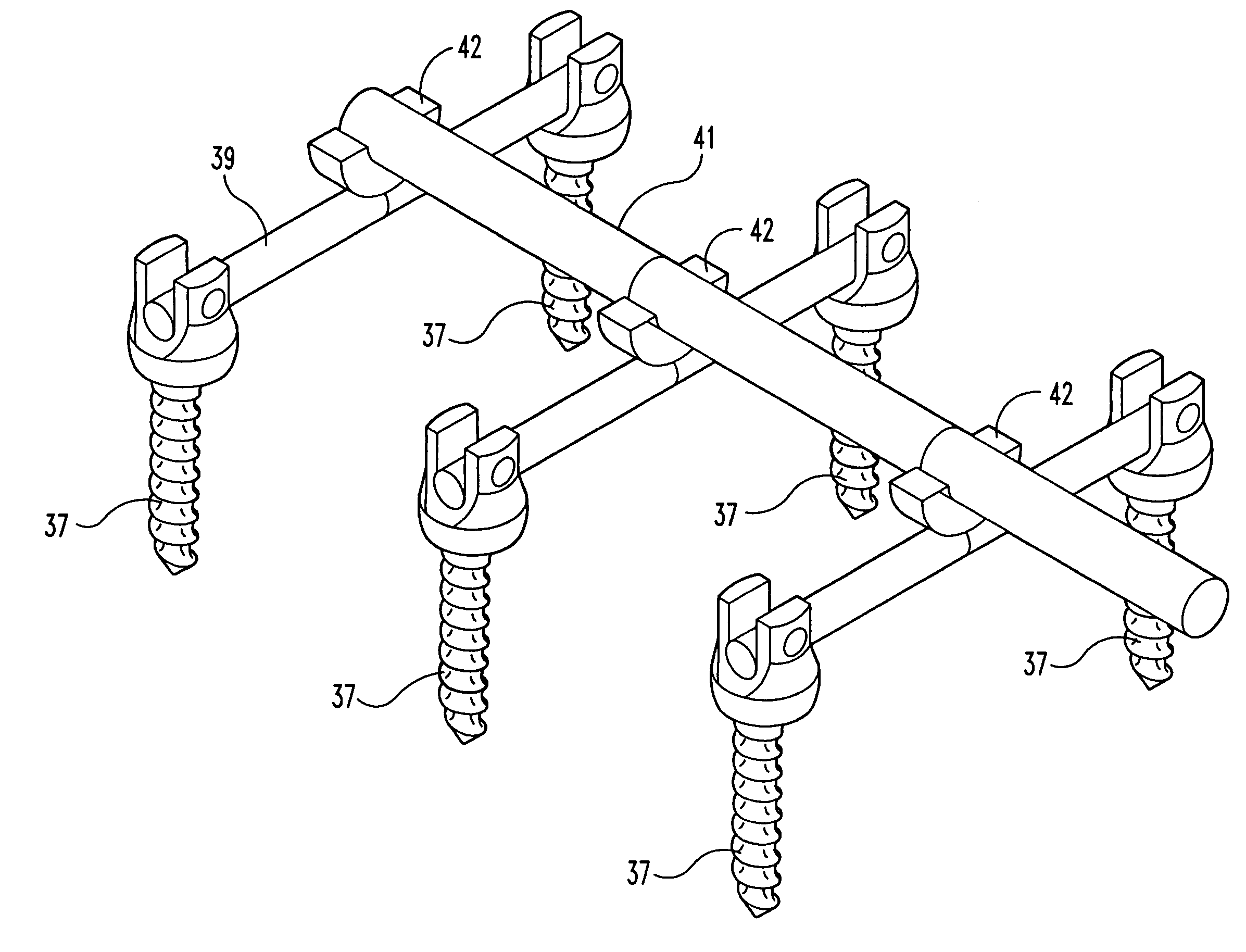
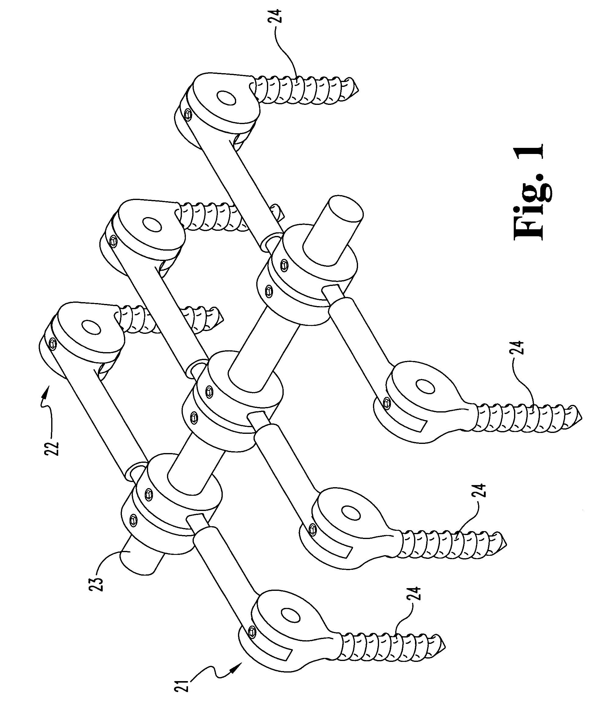
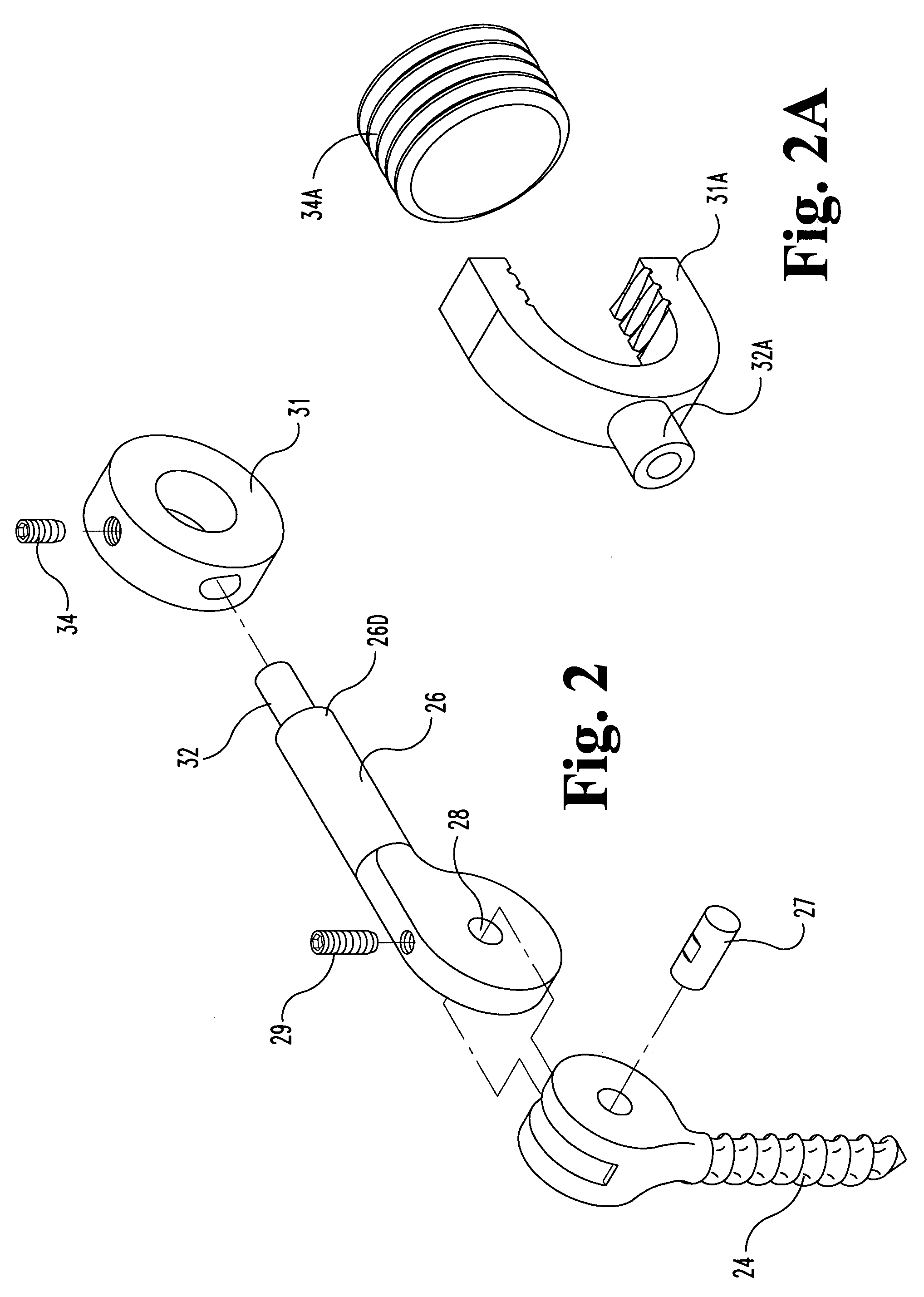
[0025]Turning now to FIGS. 1–2, one embodiment of a spinal fixation system according to the present invention includes two columns 21, 22 of pedicle screws along each side of a patient's spine and a single support rod 23 positioned between the two columns (i.e., substantially in the center of the spine) and connected to each of the pedicle screws. An example of the connection is shown in the exploded view of FIG. 2 where the pedicle screw 24 has a yoke at the top receiving a proximal end of connector arm 26 retained in the yoke by hinge pin 27, received through aperture 28 in the arm and fixed there by locking screw 29. At the distal end 26D of the arm 26, a ring 31 is connected by multi-axial hinge at 32 and through which the rod 23 is received as shown in FIG. 1 and secured in place by a locking screw 34. FIG. 2A is an example in which a multi-axial screw head 31A on stem 32A with locking screw 34A is substituted for ring 31 of FIGS. 1 and 2. Screw head and stem are of the Medtron...


PUM


Abstract

Pedicle screws are secured in two columns, one along each side of the spine. Cross support rods have ends connected to pedicle screw heads. A longitudinally extending rod is supported on the cross supports and recessed in the cavity created by removal of portions of spinous processes, providing a reduced profile of the installed construct. Several types of cross supports are shown such as: arms from the screws inward to rings or yokes connecting the longitudinal rod; cross rods with ends connected to the screws and having centrally-located yokes for the longitudinal rod; cross rods with articulating longitudinal rod portions fixed or swiveled to them. These cross rods may have end portions angled posterior toward anterior to accommodate lateral positioned pedicle screws, but shorter cross rods without angled end portions enable medialized pedicle screw orientation.

Description

CROSS REFERENCE TO RELATED APPLICATION[0001]The present invention and application claims the benefit of priority of U.S. Provisional Application No. 60 / 276,706 filed Mar. 16, 2001 which is incorporated herein directly and by reference.FIELD OF THE INVENTION[0002]The present invention relates to medical devices, and, more particularly, to spinal fixation systems and related methods.BACKGROUND OF THE INVENTION[0003]Spinal fixation systems may be used to correct and stabilize the position of vertebral segments within a patient's spine. Such correction may be necessary as a result of accidents, degenerative diseases, etc. Typical spinal fixation systems in use today include pedicle screws attached to the posterior of a patient's vertebrae in a vertical column along either one or both sides of the spine. A rod is connected to the heads of each pedicle screw in a column to provide support for the spine. Examples of such prior art devices may be seen in U.S. Pat. No. 5,741,255 entitled “Sp...

Claims


Application Information

Patent Timeline
IPC IPC(8): A61B17/56A61B17/58
CPCA61B17/7011A61B17/7023A61B17/7025A61B17/7034A61B17/7038A61B17/7043A61B17/7005A61B17/7013A61B17/7014A61B17/7041A61B17/7071
Inventor HYNES, RICHARD A.
Owner WARSAW ORTHOPEDIC INC
Why Eureka
Try Eureka