Digital camera

a digital camera and camera body technology, applied in the field of digital cameras, can solve the problems of limiting requiring the setting of the camera-shake limit, and restricting the degree of freedom in design for the electronic-charge accumulation time of the digital camera

Inactive Publication Date: 2007-05-22
ASAHI KOGAKU KOGYO KK
View PDF10 Cites 72 Cited by
  • Summary
  • Abstract
  • Description
  • Claims
  • Application Information

AI Technical Summary

Benefits of technology

The present invention provides a digital camera with a solid state imaging device that has a program to control the time it takes to accumulate electronic charge. This program is based on the camera's shake limit, which determines the optimal time to capture images without shaking. The technical effect of this invention is to improve image quality and stability by reducing camera shake.

Problems solved by technology

The technical problem addressed in this patent is how to properly expose a digital camera's sensor while accounting for camera-shake caused by movement during photography. In traditional methods, a shutter speed program was designed to achieve optimal exposure by measuring the amount of motion present through analysis of images captured from a series of frames. However, these techniques were limited to specific types of sensors and did not consider variations in pixel spacing between pixels in different cameras. Consequently, the resulting settings may be too restrictive, leading to poor quality photos taken under certain conditions.

Method used


Image

  • Digital camera
  • Digital camera
  • Digital camera

Examples


first embodiment

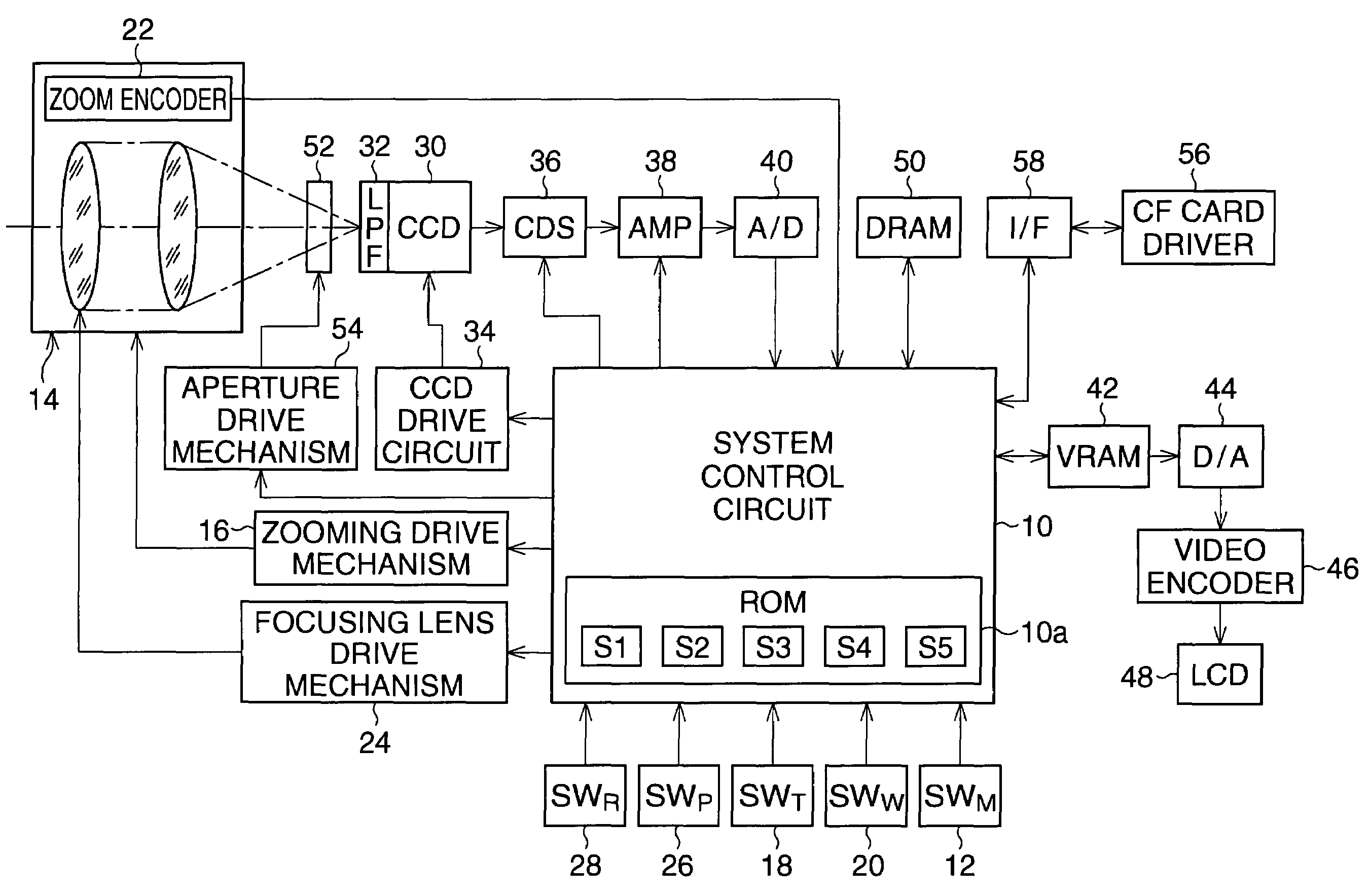
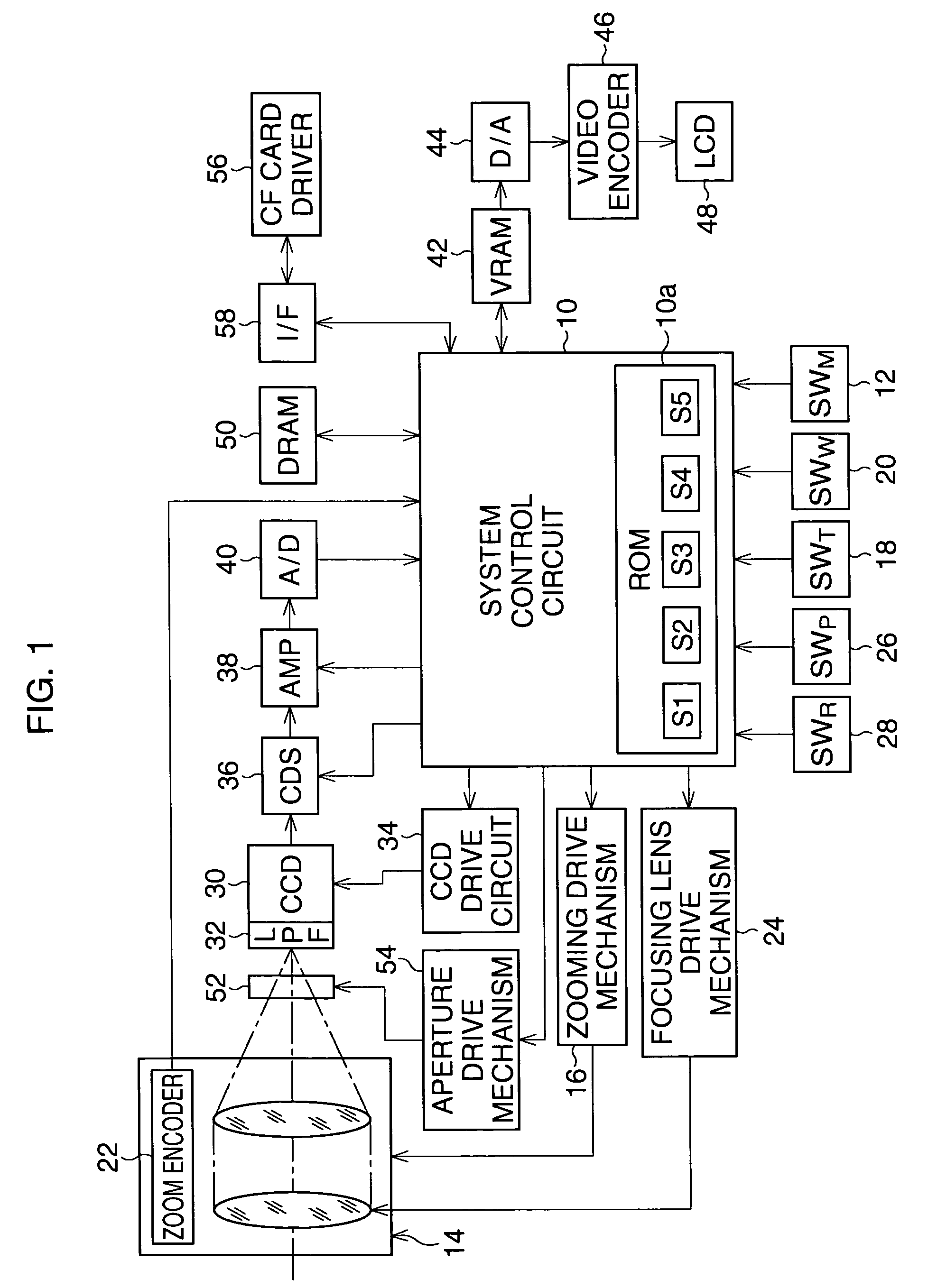
[0027]FIG. 1 shows a block diagram of a digital camera to which the present invention is applied. In the digital camera, a system control circuit 10 is provided to control the digital camera as a whole. The system control circuit has a micro-computer for controlling a CPU, a ROM for storing constants and a program for performing various kinds of routines, a RAM for temporarily storing data and so on, and an I / O interface.

[0028]The system control circuit 10 has a main switch (SWM) 12, by which a sleep mode or a photographing mode is selected. Namely, when a battery (not shown) is mounted in the digital camera, the system control circuit 10 is operated in the sleep mode (i.e., a minimum power consumption state), so that it is monitored at a predetermined time interval only whether the main switch 12 is turned ON. When the main switch 12 is turned ON, the mode is changed from the sleep mode to the photographing mode, a photographing process routine is executed by the system control cir...

second embodiment

[0088]Note that, in the second embodiment, the gain of the amplifier 38 is controlled in such a manner that a moving picture is indicated with a predetermined brightness on the LCD panel 48, while the LCD panel indication process routine is executed in Step 801.

[0089]In the above embodiments, the electronic-charge accumulation-time is controlled using an electronic shutter operated in a solid state imaging device such as a CCD. Conversely, in a case of a digital camera in which a mechanical shutter is assembled similar to a silver halide film camera, the shutter speed is set in order to prevent a camera-shake from occurring, instead of an electronic-charge accumulation-time.


PUM


Abstract

A digital camera comprises a solid state imaging device provided with an optical low-pass filter. A photographing optical system forms an object image on a light receiving surface of a CCD through the optical low-pass filter. An electronic-charge accumulation-time control program is stored in a ROM of a system control circuit to determine optimum exposure parameters according to which a photography is performed. The electronic-charge accumulation-time control program has a program diagram showing a relationship between an electronic-charge accumulation-time and an aperture value and/or an ISO speed.

Description


Claims


Application Information

Patent Timeline
Owner ASAHI KOGAKU KOGYO KK
Why Eureka
Try Eureka