Down-converter and up-converter for time-encoded signals

Active Publication Date: 2009-06-04
HRL LAB
View PDF7 Cites 86 Cited by
  • Summary
  • Abstract
  • Description
  • Claims
  • Application Information

AI Technical Summary

Benefits of technology

[0023]It is preferred that the receiver system can operate effectively with signals in the radio frequency range. In certain e

Problems solved by technology

This reduction is problematic for traditional analog-to-digital conversion schemes because of the reduction in the resolution available within t

Method used


Image

  • Down-converter and up-converter for time-encoded signals
  • Down-converter and up-converter for time-encoded signals
  • Down-converter and up-converter for time-encoded signals

Examples


example 1

Simulation Results of a Filter with a Down-Converter Provided by the Invention

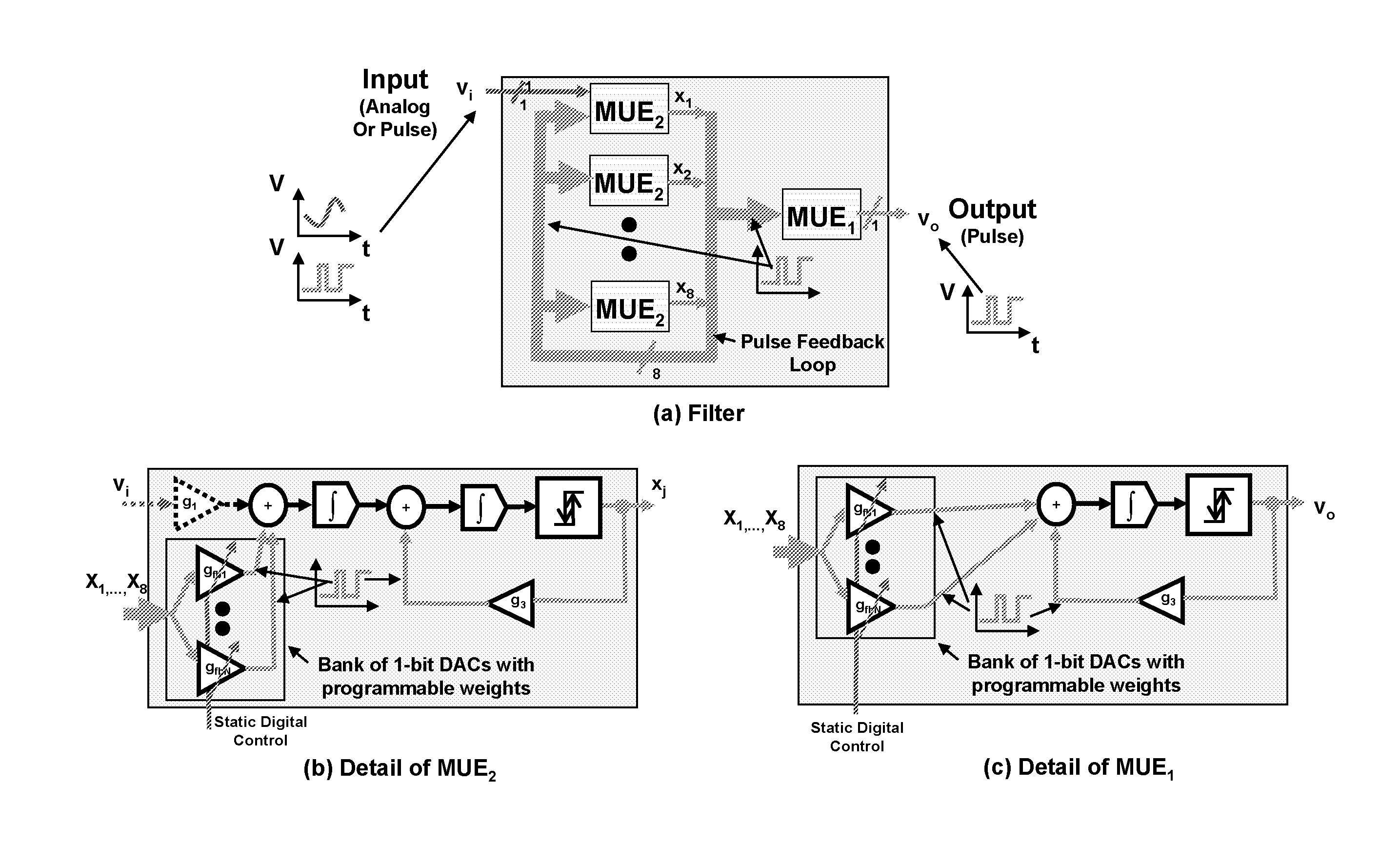
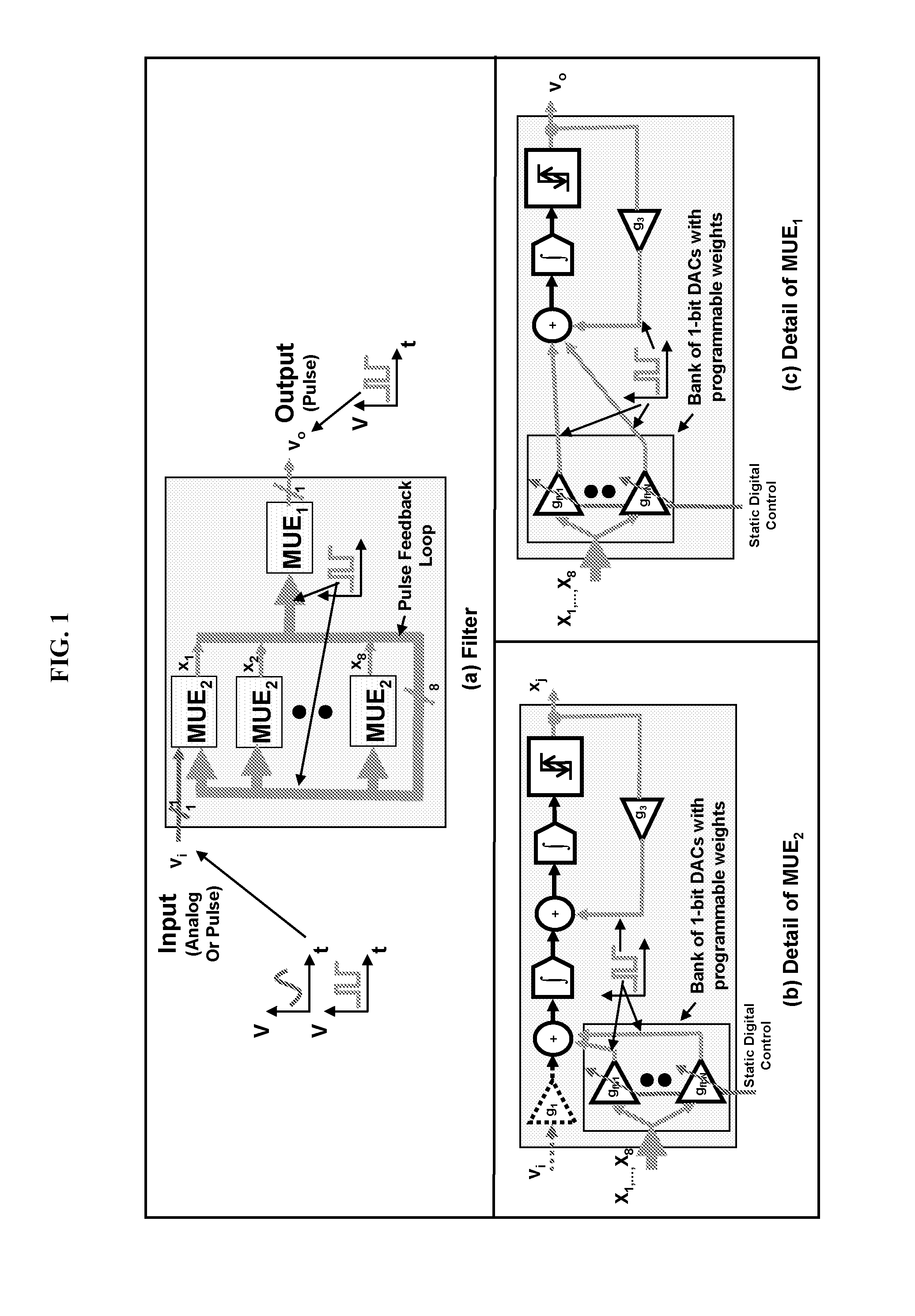
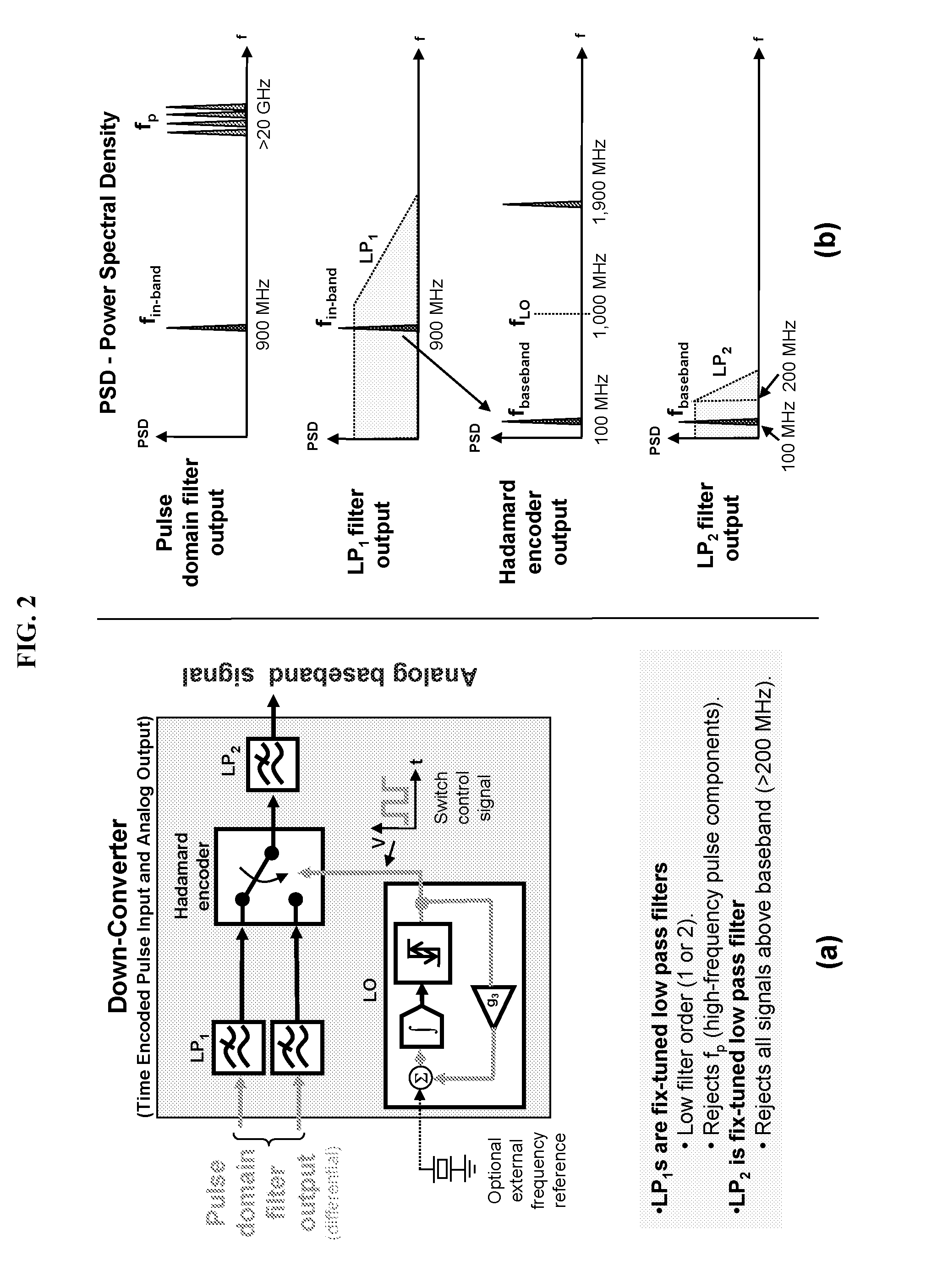
[0062]In this example, a simulation of the circuit using multi-tone input signals is carried out. The model for the simulation includes an input multi-tone analog signal; a filter similar to that shown in FIG. 1 but with differential output that is time-encoded; and a down-converter circuit as shown in FIG. 2.

[0063]FIG. 5 shows the simulated transfer characteristic of the time-encoding filter. In this example, the weights of the filter are adjusted to produce a narrowband band-pass characteristic with a bandwidth of 20 MHz centered at 900 MHz. The output of this filter is used to test a circuit of the invention. The data of FIG. 5 was extracted from a Fast Fourier Transform (FFT) of a time-domain simulation of the impulse response of the filter.

[0064]FIG. 6 shows the simulation results. All the graphs were generated via FFT from time-domain simulation data. FIG. 6(a) shows the spectrum of the analog input ...


PUM


Abstract

The disclosed invention provides apparatus and methods that can convert frequencies of time-encoded signals. In one aspect, a down-converter circuit includes low-pass filters, a switch, a time encoder, and an output low-pass filter. In another aspect, an up-converter circuit includes an analog or digital input time encoder, low-pass filters, a switch, an output time encoder, and a time-encoded band-pass filter. In yet another aspect, a complete receiver system is provided. The receiver system can operate effectively with signals in the radio frequency range.

Description

FIELD OF THE INVENTION[0001]The present invention generally relates to communication systems. More specifically, the present invention relates to apparatus and methods that can convert frequencies of time-encoded signals.BACKGROUND OF THE INVENTION[0002]The continuing decrease in the minimum feature size of modern complementary metal-oxide-semiconductor processes has necessitated a reduction in the circuit supply voltage for reliability and power-dissipation reasons. This reduction is problematic for traditional analog-to-digital conversion schemes because of the reduction in the resolution available within the amplitude range. On the other hand, the decrease in the minimum feature size has a beneficial effect on the obtainable time resolution in the circuitry, owing to the increase in the intrinsic speed of the transistors. Therefore, it is of interest to turn over the amplitude axis to the time axis and to encode information in the latter rather than the former (Roza, IEEE Transac...

Claims


Application Information

Patent Timeline
IPC IPC(8): H04B7/14H04B3/36
CPCH04L25/03834H04L2027/0024H04L27/0014H04L25/38
Inventor CRUZ-ALBRECHT, JOSEPETRE, PETER
Owner HRL LAB
Why Eureka
Try Eureka