
System for determining communication parameters associated with an unknown digital printer

Inactive Publication Date: 2007-06-05
XEROX CORP
View PDF6 Cites 5 Cited by
  • Summary
  • Abstract
  • Description
  • Claims
  • Application Information

AI Technical Summary

Problems solved by technology

However, the system is limited to printer port number 9100 Raw printing, which is a standard on all the HP printer models.

Method used


Image

  • System for determining communication parameters associated with an unknown digital printer
  • System for determining communication parameters associated with an unknown digital printer
  • System for determining communication parameters associated with an unknown digital printer

Examples


Embodiment Construction

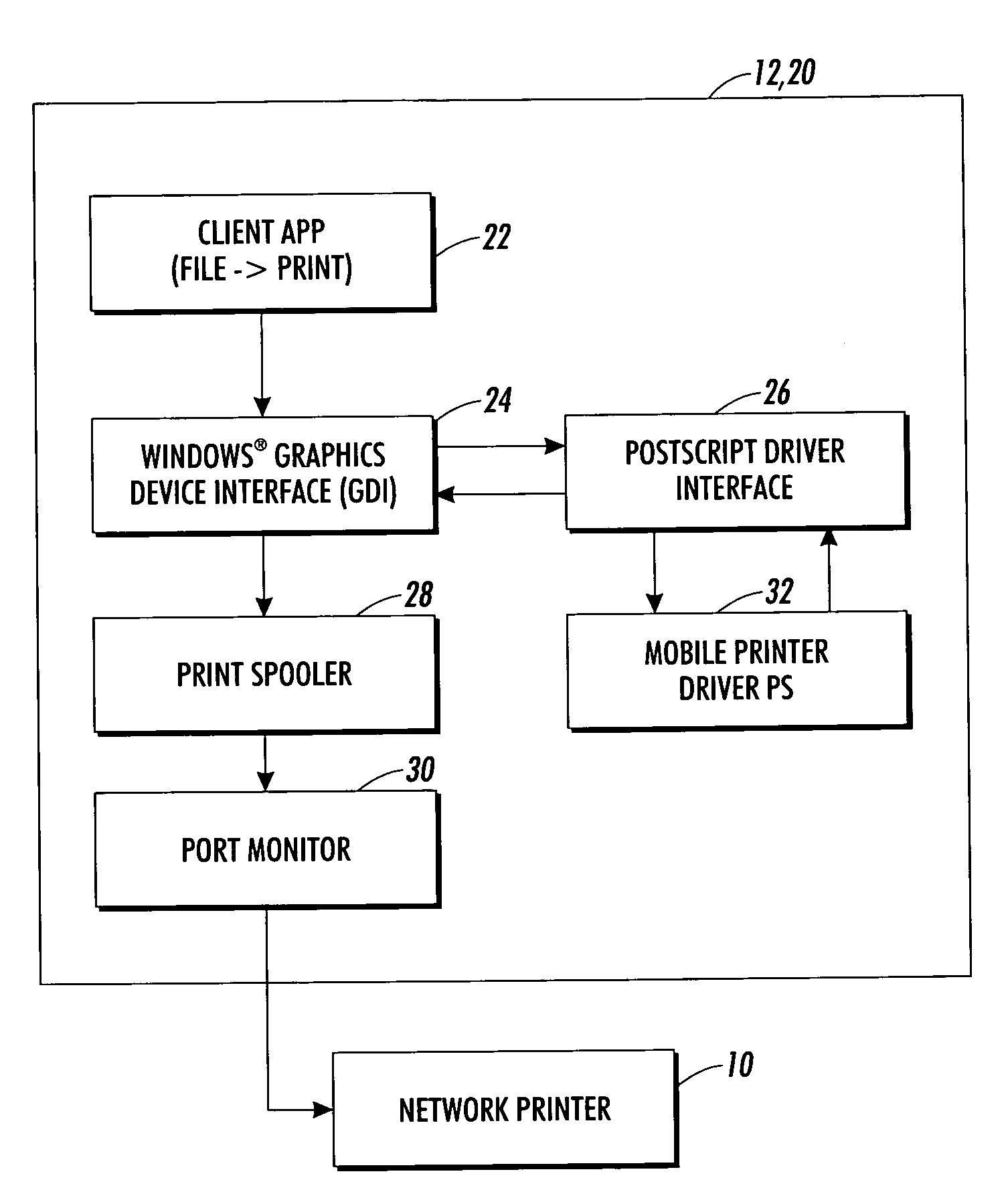
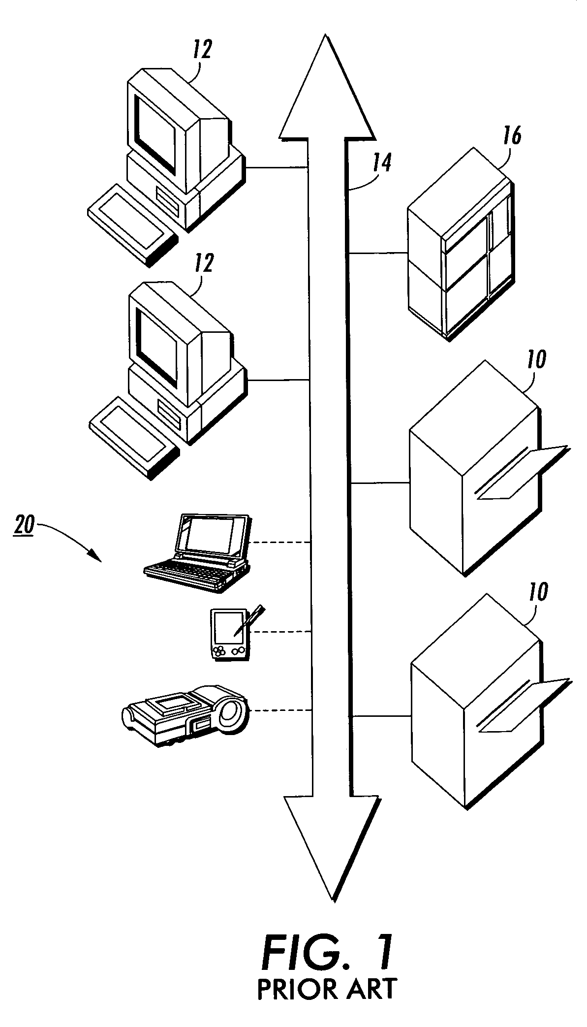
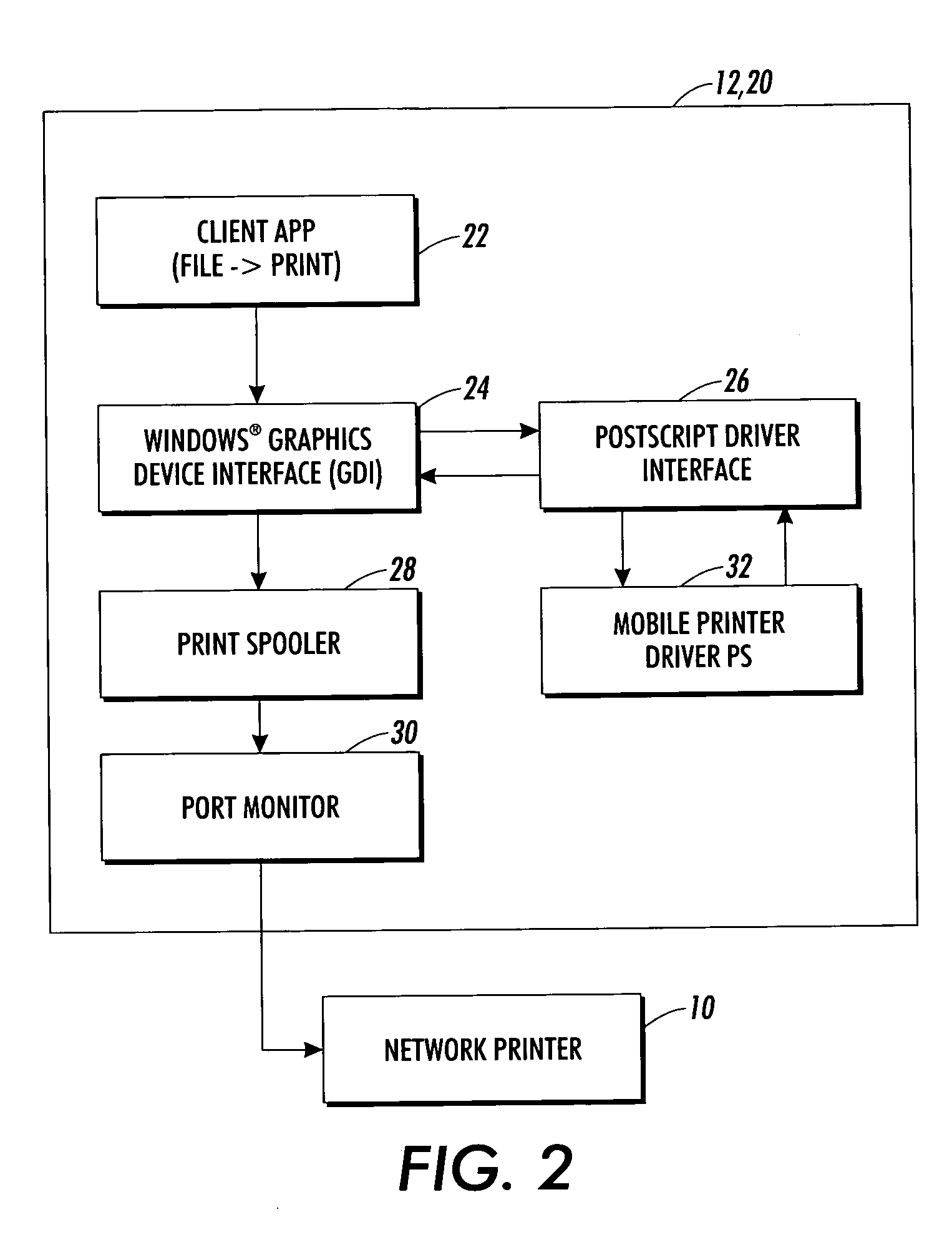
[0015]FIG. 1 is a simplified diagram showing a context of network printing, as generally familiar in the prior art. As is familiar in the art, in a typical office building, any number of digital printers, such as 10, can receive image data from one of any number of computers, such as 12, via a network 14, which is typically controlled by a network server 16. Typically, each user of a computer 12 can choose, through a user interface, which digital printer he would like to print a particular job with. The network server 16 retains the internet address and other settings associated with each computer 12 and printer 10, so that, as needed, any computer 12 can “find” and operate a desired printer 10.

[0016]Also shown in FIG. 1 is any number of what generically be called “portable computers” such as digital cameras, laptop or tablet computer,PDA's, and other devices, known now or which will be developed in the future, which are capable of sending out data desired to be printed; these types...


PUM


Abstract

A port monitor allows a computer, digital camera, or other device to send a print job to a target printer, where the only known information about the printer is its network address. Communication is attempted to the network address, sequentially using each of a plurality of port numbers. If none of the plurality of port numbers is successful in initiating communication to the network address, communication to the network address is attempted using an LPR port number, sequentially using each of a plurality of LPR queue names.

Description

CLAIM OF PRIORITY TO PROVISIONAL APPLICATION[0001]This application claims the benefit of U.S. Provisional Application No. 60 / 448,303, filed Feb. 14, 2003, the disclosure of which is totally incorporated herein by reference.INCORPORATION BY REFERENCE[0002]The following U.S. Published Patent Application is hereby incorporated by reference for the teachings therein: 20020196463, which is based on U.S. patent application Ser. No. 10 / 106,140, filed Mar. 25, 2002.TECHNICAL FIELD[0003]The present invention relates to digital printing over a network, particularly in the communication between a computer having a job to be printed and a target printer.BACKGROUND[0004]The basic model of digital printing over a network is well known. A population of computers, each of which may hold document data which is desired to be printed, communicates with a population of digital printers, using a print protocol such as Raw or LPR (Line Printer Request) over TCP / IP. An IP network address of a “target prin...

Claims


Application Information

Patent Timeline
IPC IPC(8): G06F3/00G06F13/12H04N1/00
CPCH04N1/00278
Inventor SCHLONSKI, STEVEN T.DEROLLER, MATTHEWKUMAR, KRISHNA
Owner XEROX CORP
Learn More