Release capsule for steering column

a technology of steering column and release capsule, which is applied in the direction of steering column, steering parts, vehicle components, etc., can solve the problems of achieve the effect of reducing vibrations transmitted to the steering wheel, reliable precision, and high frequency value of the steering column

Inactive Publication Date: 2007-06-12
STEERING SOLUTIONS IP HLDG +1
View PDF17 Cites 14 Cited by
  • Summary
  • Abstract
  • Description
  • Claims
  • Application Information

AI Technical Summary

Benefits of technology

[0006]According to one aspect of the subject invention, a vehicular steering column assembly comprises an outer sleeve which defines a longitudinal axis and has an upper end proximate the steering wheel. An inner steering shaft is rotatably carried in the sleeve. A support bracket fixedly joins the sleeve adjacent its upper end to a vehicle body. The support bracket has a releasable mounting surface. A release capsule is provided for fixed connection to a vehicle body and engages the mounting surface of the support bracket for automatically releasing therefrom upon the application of sufficient force along the longitudinal axis of the sleeve. At least one of the mounting surface and the release capsule has a crown protruding therefrom and the other of the mounting surface and the release capsule has a furrow generally parallel to the longitudinal axis and corresponding in shape to the crown. The crown is seated in the furrow such that upon automatic release of the release capsule from the mounting surface, the crown moves (relatively) along the furrow. This arrangement improves release force predictability during collision and improves resonance control over the steering column assembly during normal operation.
[0007]The crown and furrow feature of this invention provides a highly predictably release force which can be calculated by the static and dynamic friction factors which exist between the surface of the crown sliding within the furrow. Contrary to the prior art, this crown and furrow feature is not subject to variables inherent in plastic injection techniques, and by design is capable of providing a stiffer connection by which the frequency value of the steering column can be increased thus avoiding resonance with the engine.
[0008]According to another aspect of the invention, a safety release assembly for a vehicular steering column is provided. The safety release assembly is of the type for automatically releasing the steering column from the vehicle structure upon the application of sufficient axial force. The safety release assembly comprises a support bracket for attachment to a steering column. The support bracket has a releasable mounting surface. A release capsule is provided for fixed connection to a vehicular body. The release capsule engages the mounting surface of the support bracket and automatically releases therefrom upon the application of sufficient force. At least one of the mounting surface and the release capsule has a crown protruding therefrom, and the other of the mounting surface and the release capsule has an elongated furrow corresponding in shape to the crown. The crown is seated in the furrow such that upon automatic release of the release capsule from the mounting member, the crown moves (relatively) along the furrow thereby improving release force predictability during a collision and improving resonance control over the steering column during normal operation.
[0011]The subject crown and furrow configuration, and its corresponding method, provide a connection between a steering column and a body of a motor vehicle in which the release force needed to disconnect the steering column from the motor vehicle body during a collision can be calculated with reliable precision. Additionally, the crown and furrow configuration enables a stiffer mounting of the steering column to the vehicle body, thus resulting in a higher frequency value for the steering column and reduced vibrations transmitted to the steering wheel.

Problems solved by technology

This can, in certain circumstances, result in vibrations transmitted to the steering wheel which can be felt by a driver.

Method used


Image

  • Release capsule for steering column
  • Release capsule for steering column
  • Release capsule for steering column

Examples


Embodiment Construction

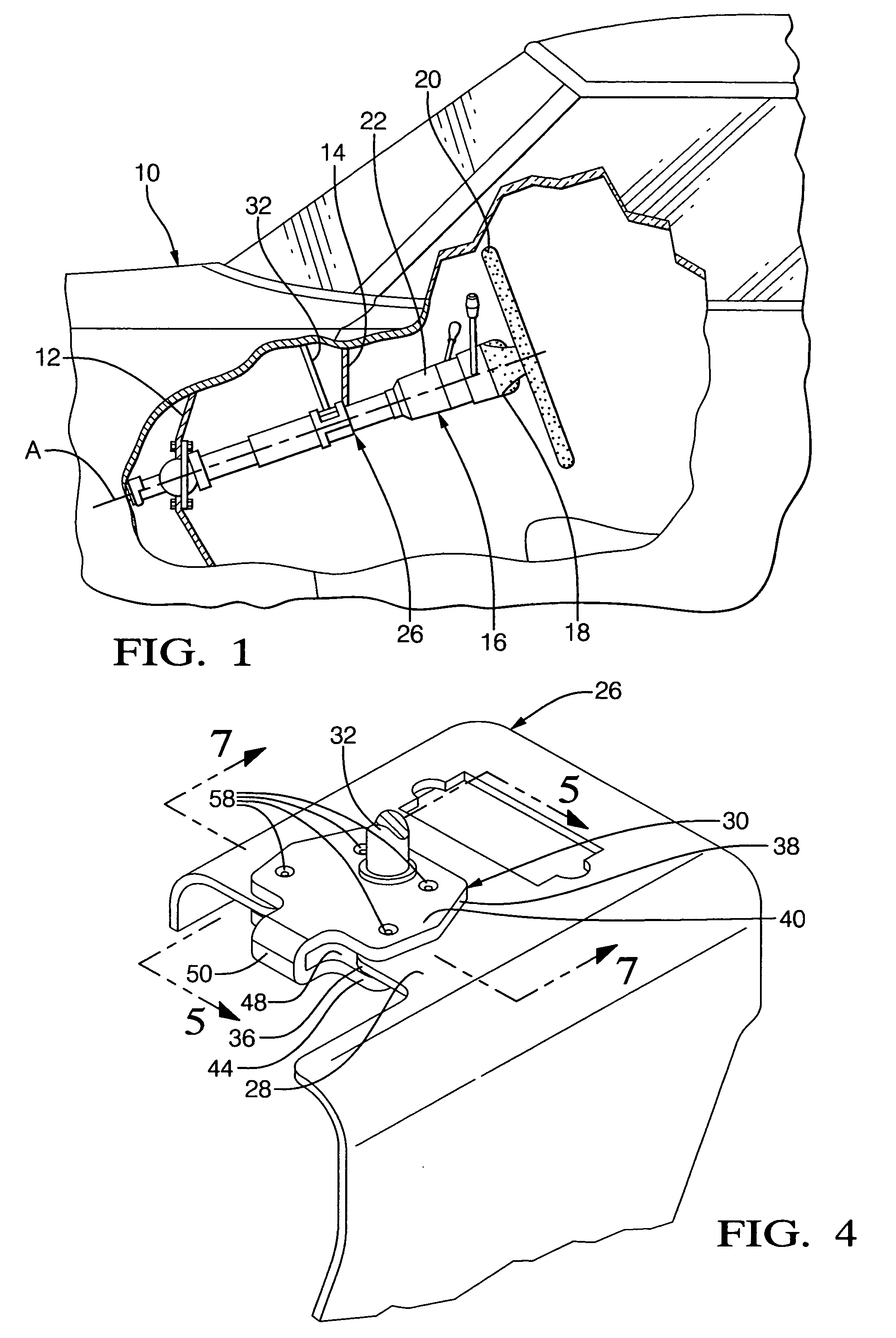
[0026]Referring to the figures, wherein like numerals indicate like or corresponding parts throughout the several views, a representation of a typical motor vehicle is generally indicated at 10 in FIG. 1.

[0027]The motor vehicle 10 includes the typical firewall 12 and dashboard structure 14 which together form part of the vehicle body. A typical vehicular steering column assembly is generally indicated at 16 in FIG. 1. The steering column assembly 16 may be supported at multiple points upon the vehicle body such as, in the example of FIG. 1, between the firewall 12 and under the dashboard 14. The steering column assembly 16 may be of the non-adjustable type, or of the type which can be adjusted by tilt, by rake, and / or by telescoping movement. Adjacent the upper end 18 of the steering column 16 is provided a steering wheel 20.

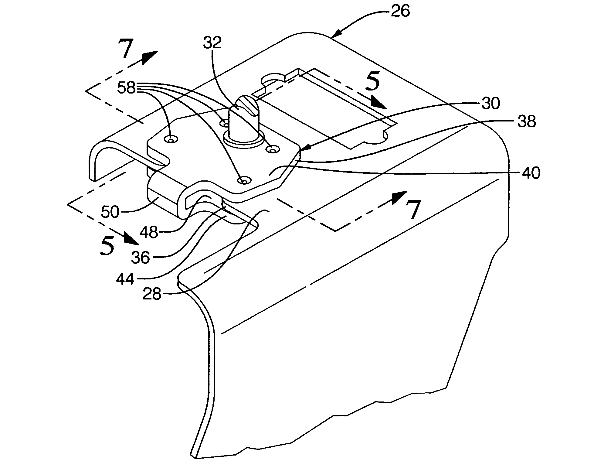
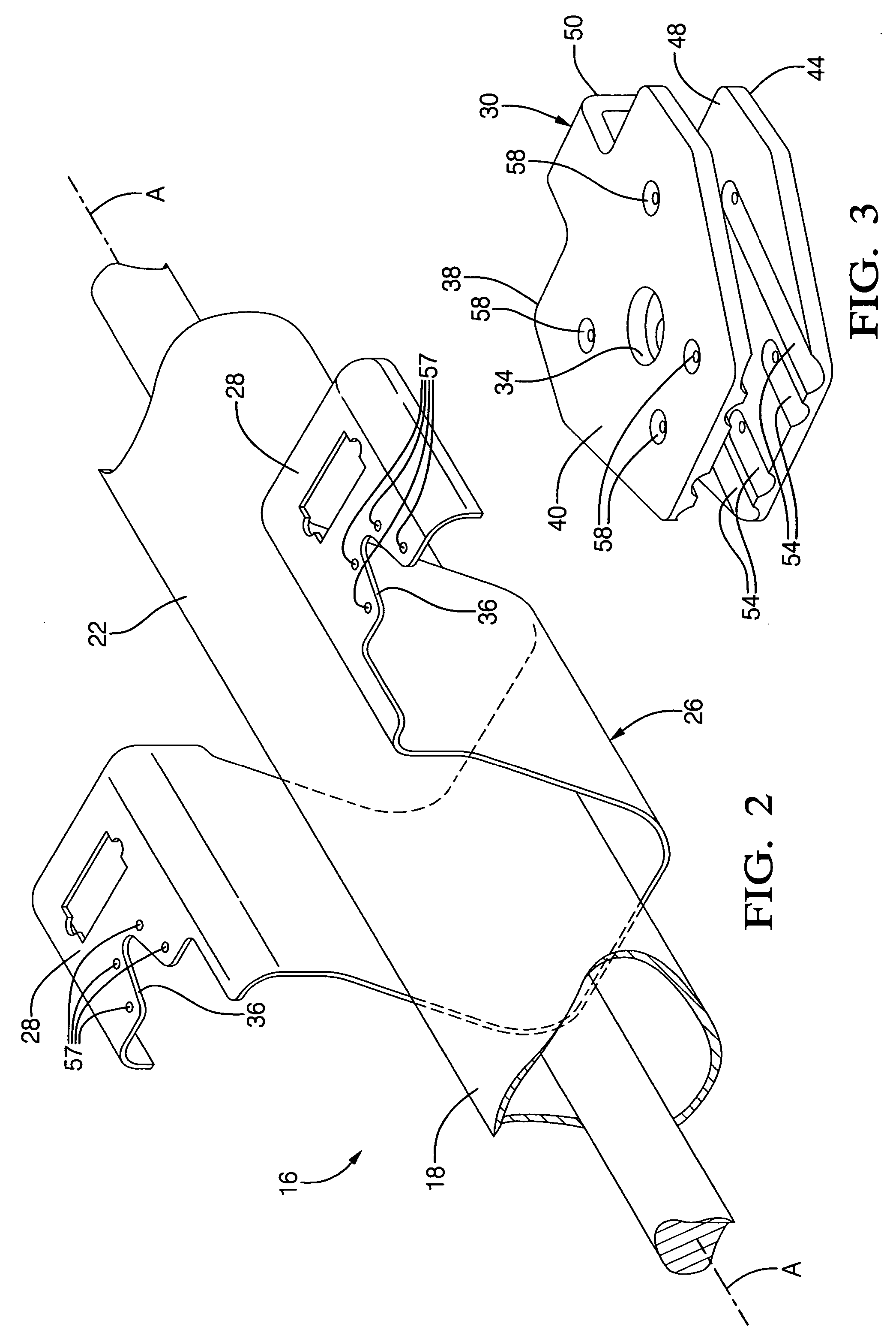
[0028]Referring now to FIG. 2, the steering column assembly 16 is shown including an outer sleeve 22 which defines a longitudinal axis A. An inner steering shaf...


PUM


Abstract

A vehicular steering column assembly (16) comprises a support bracket (26) which is joined to an outer, non-rotating sleeve (22). A release capsule (30) is releasably joined to a mounting surface (28) of the support bracket (26) via a plurality of spherical bodies (56) whose protruding crowns (52) are seated in corresponding longitudinally-extending furrows (54) in the release capsule (30). Upon the application of sufficient force to the steering column (16), such as during a collision, the support bracket (26) is urged out of engagement with the release capsule (30) with the respective furrows (54) sliding over the crowns (52). The sliding engagement between the crowns (52) and the furrows (54) can be adjusted to establish a highly predictable and consistent release force and which is capable of increasing the frequency value for the steering column (16).

Description

FIELD OF THE INVENTION[0001]This invention relates to a steering column assembly for a motor vehicle, and more specifically to an improved connection between the steering column and the vehicle body.BACKGROUND OF THE INVENTION[0002]Steering columns for motor vehicles are designed to collapse longitudinally through an energy absorbing stroke in response to an impact on the steering column. For example, in a frontal collision, a driver's chest may impact the steering wheel, causing an axial force along the steering column. The connection which holds the steering column to the motor vehicle body is designed to release in a collision to prevent or reduce injury to the driver's chest.[0003]One typical method of accomplishing this releasable connection is to provide a support bracket on the outer, non-rotating sleeve of the steering column. The support bracket is designed with a releasable mounting surface. A release capsule, in turn, is fixed to the vehicle body and engages the mounting ...

Claims


Application Information

Patent Timeline
Patent Type & Authority Patents(United States)
IPC IPC(8): B62D1/18
CPCB62D1/195
Inventor ARMSTRONG, RAY G.RIEFE, RICHARD K.JWALAPATHY, RAVINDRA
Owner STEERING SOLUTIONS IP HLDG
Why Eureka
Try Eureka