Micro-Infusion System

a micro-infusion system and pump technology, applied in the field of medical infusion systems, can solve the problems of unsatisfactory solutions for high-throughput micro-infusion pumps, such as infusion pumps, used in the health and medical industry, and the vaporization of dissolved gas within the fluid flow path of the infusion pump system is a significant health risk to patients receiving infusion, and achieves a wide range of flow rates , high degree of accuracy and predictability, and facilitates th

Inactive Publication Date: 2012-09-27
SIMS CO LTD
View PDF1 Cites 61 Cited by
  • Summary
  • Abstract
  • Description
  • Claims
  • Application Information

AI Technical Summary

Benefits of technology

[0009]Infusion systems according to the present invention provide a medical fluid infusion system that achieves a relatively wide range of flow rates while maintaining a high degree of accuracy and predictability. Infusion systems according to the present invention achieve these advances by employing specific flow path architecture, flow path dimensional ranges, and pump control parameters, such as voltage, frequency, voltage rise time, pump size and quantity, and controlled restriction of the fluid flow path for generation of back pressure and controlling such characteristics and parameters relative to one another.
[0010]In certain embodiments, infusion systems according to the present invention achieve automatic recognition of restrictive elements, thereby facilitating the ease of use of different restrictive elements with a single infusion system and improving patient safety.
[0011]In another embodiment of the present invention, the infusion system is incorporated into a fluid bag thereby streamlining the infusion system for bed-side or mobile usage.

Problems solved by technology

The vaporization of dissolved gas within the fluid flow paths of infusion pump systems presents a significant health hazard to patients receiving infusions.
While the problems associated with the vaporizations of dissolved gas in inkjet printer micropumps, systems in which fluid throughputs are relatively low, has largely been addressed through the development of degassing technologies, satisfactory solutions have not been presented for high-throughput micropumps, such as infusion pumps, used in the health and medical industry.
U.S. Publication No. 2006 / 0264829 to Donaldson and U.S. Pat. No. 5,205,819 to Ross et al. described large-volume infusion systems employing piezoelectric micropumps; however, neither of these systems provides solutions directed to overcoming the problems associated with vaporization of dissolved gas at high fluid throughputs.

Method used


Image

  • Micro-Infusion System
  • Micro-Infusion System
  • Micro-Infusion System

Examples


Embodiment Construction

[0031]Specific embodiments of the invention will now be described with reference to the accompanying drawings. This invention may, however, be embodied in many different forms and should not be construed as limited to the embodiments set forth herein; rather, these embodiments are provided so that this disclosure will be thorough and complete, and will fully convey the scope of the invention to those skilled in the art. The terminology used in the detailed description of the embodiments illustrated in the accompanying drawings is not intended to be limiting of the invention. In the drawings, like numbers refer to like elements.

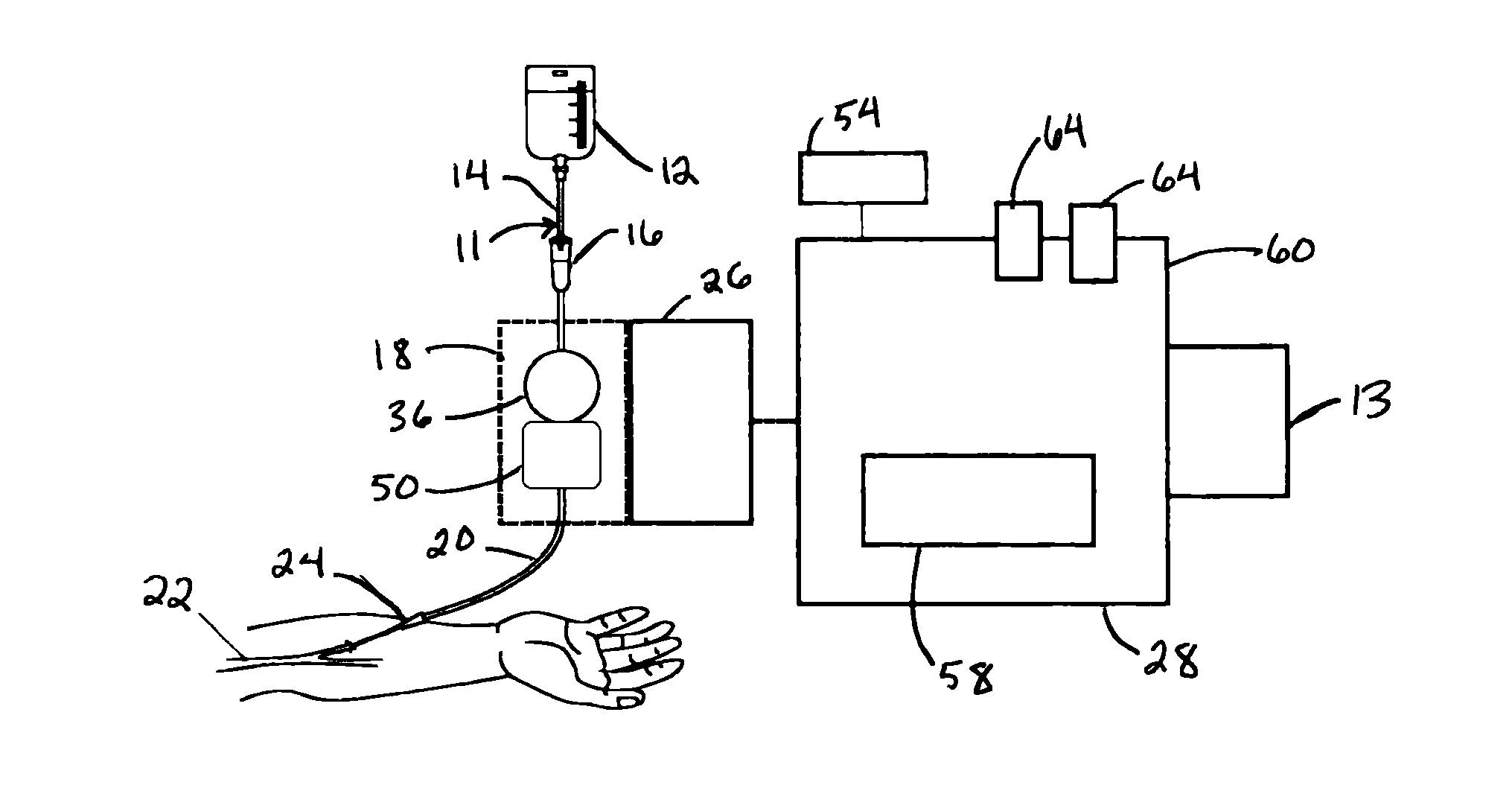
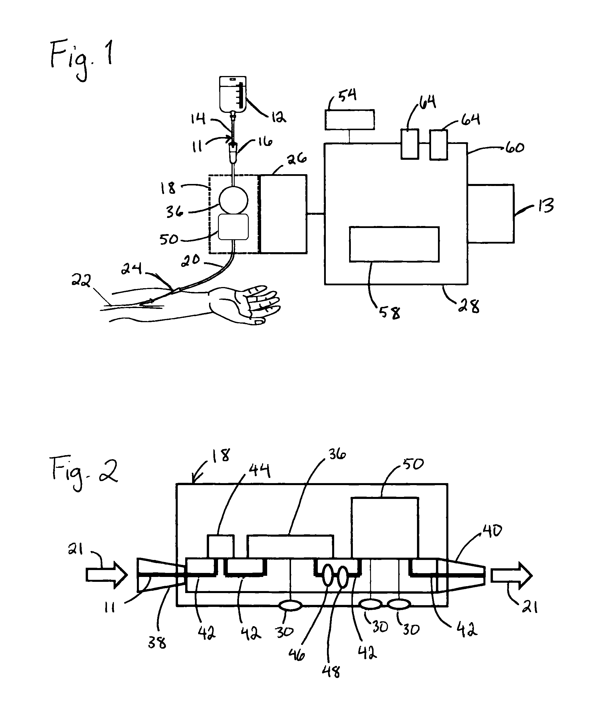
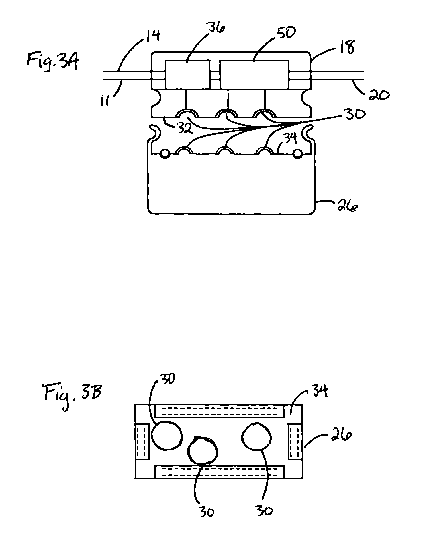
[0032]As shown in FIG. 1, a generalized overview of an infusion systems or micro-infusion system 10 according to the present invention includes a patient fluid flow path 11 comprising an administrative set or tube set 14, a pump core 18, a patient line 20, and a connector 24. The administrative set 14 provides fluid communication between an infusion bag 12 and...


PUM


Abstract

Infusion systems according to the present invention provide a medical fluid infusion system operable at a relatively wide range of flow rates while simultaneously maintaining a high degree of accuracy and predictability through employing specific flow path architecture, flow path dimensional ranges, and pump control parameters, such as voltage, frequency, voltage rise time, pump size and quantity, and controlled restriction of the fluid flow path. Automatic recognition of restrictive elements is employed to facilitate the ease of use of different restrictive elements with a single infusion system and improve patient safety.

Description

RELATED APPLICATIONS[0001]This application claims priority to U.S. Provisional Application Ser. No. 61 / 611,452 filed Mar. 15, 2012, entitled Infusion System; U.S. Provisional Application Ser. No. 61 / 566,542 filed Dec. 2, 2011, entitled Infusion Pump; and U.S. Provisional Application Ser. No. 61 / 453,909 filed Mar. 17, 2011, entitled Infusion Pump, each of which is hereby incorporated herein by reference in its entirety.FIELD OF THE INVENTION[0002]The present invention relates to medical infusion systems and related methods and, more particularly, to infusion systems employing a piezoelectric effect for medical and healthcare related applications.BACKGROUND OF THE INVENTION[0003]Fluid pumps can be driven based on various design principles including the piezoelectric effect. The piezoelectric effect can be employed to indirectly cause fluid flow, for example a piezoelectric driven motor or actuator can be used to linearly displace a plunger to push fluid from a reservoir or to rotate a...

Claims


Application Information

Patent Timeline
Patent Type & Authority Applications(United States)
IPC IPC(8): A61M5/168A61M5/142
CPCA61M5/141A61M5/1413A61M5/142A61M2205/0244A61M2205/33G06F19/3468A61M5/36G16H20/17
Inventor KAWAMURA, YASUHIRO
Owner SIMS CO LTD
Why Eureka
Try Eureka