Light-emitting diode illumination system for an optical observation device, in particular a stereomicroscope or stereo surgical microscope

a technology of light-emitting diodes and illumination systems, which is applied in the direction of lighting and heating apparatus, instruments, optical elements, etc., can solve the problems of not being able to individually control individual leds, light intensity, and relatively bulky, and achieve no increase in space requirements

Active Publication Date: 2007-06-12
LEICA INSTR SINGAPORE PTE
View PDF16 Cites 50 Cited by
  • Summary
  • Abstract
  • Description
  • Claims
  • Application Information

AI Technical Summary

Benefits of technology

[0014]With the aid of these fiber-optic components, the light-emitting diodes can now also be arranged remotely from the microscope. This yields the advantage that the microscope body can be made small and light. A further advantage is the elimination of the need to place a frosted disk immediately in front of the optical system as a diffuser, since the scattering function of the frosted disk is taken over by the light-guiding fibers.
[0018]The light coupler can also comprise a light-guiding rod system. If the light-guiding rods are correspondingly short, this yields the advantage of a compact design.
[0020]The spectrum of the illuminating light can furthermore be freely selected by electrical brightness regulation of the individual light-emitting diodes; no filters are necessary. It would be possible, for example, temporarily to use only the red-light-emitting LED to produce a returned light (red reflection) in ophthalmology, or only the green-light-emitting LED for red-free observation. “Blue light hazard” can be reduced by reducing the emission of the blue-light-emitting LED.
[0023]According to a refinement, a further fiber bundle can also be provided for feedback purposes. This fiber bundle receives, at the distal end of the fiber bundle (i.e. at the end located opposite the light source), the light reflected from the specimen and conveys it to a sensor that detects the light color and brightness. This information can thus be made available for evaluation, or used for control purposes. For example, any desired spectra can be preselected using a computer, and then compared with the measured ones. Deviations are compensated for by discrete activation and regulation of the respective color LEDs. This allows the generation of any desired illumination spectra deviating from the Planck radiation spectrum.

Problems solved by technology

These are not, however, bright enough for this application.
The individual LEDs are not, however, individually controllable; they can only be switched on and off.
This illumination apparatus offers a high light intensity, but is relatively bulky.
A further disadvantage is the high alignment accuracy of the dichroic mirrors required to ensure good and constant color accuracy.
The disadvantages of tungsten lamps, halogen lamps, etc., as used hitherto for microscopes, are principally high thermal dissipation, high power consumption and short service life, little robustness, large space requirement, and heavy weight (cf.

Method used


Image

  • Light-emitting diode illumination system for an optical observation device, in particular a stereomicroscope or stereo surgical microscope
  • Light-emitting diode illumination system for an optical observation device, in particular a stereomicroscope or stereo surgical microscope
  • Light-emitting diode illumination system for an optical observation device, in particular a stereomicroscope or stereo surgical microscope

Examples


Embodiment Construction

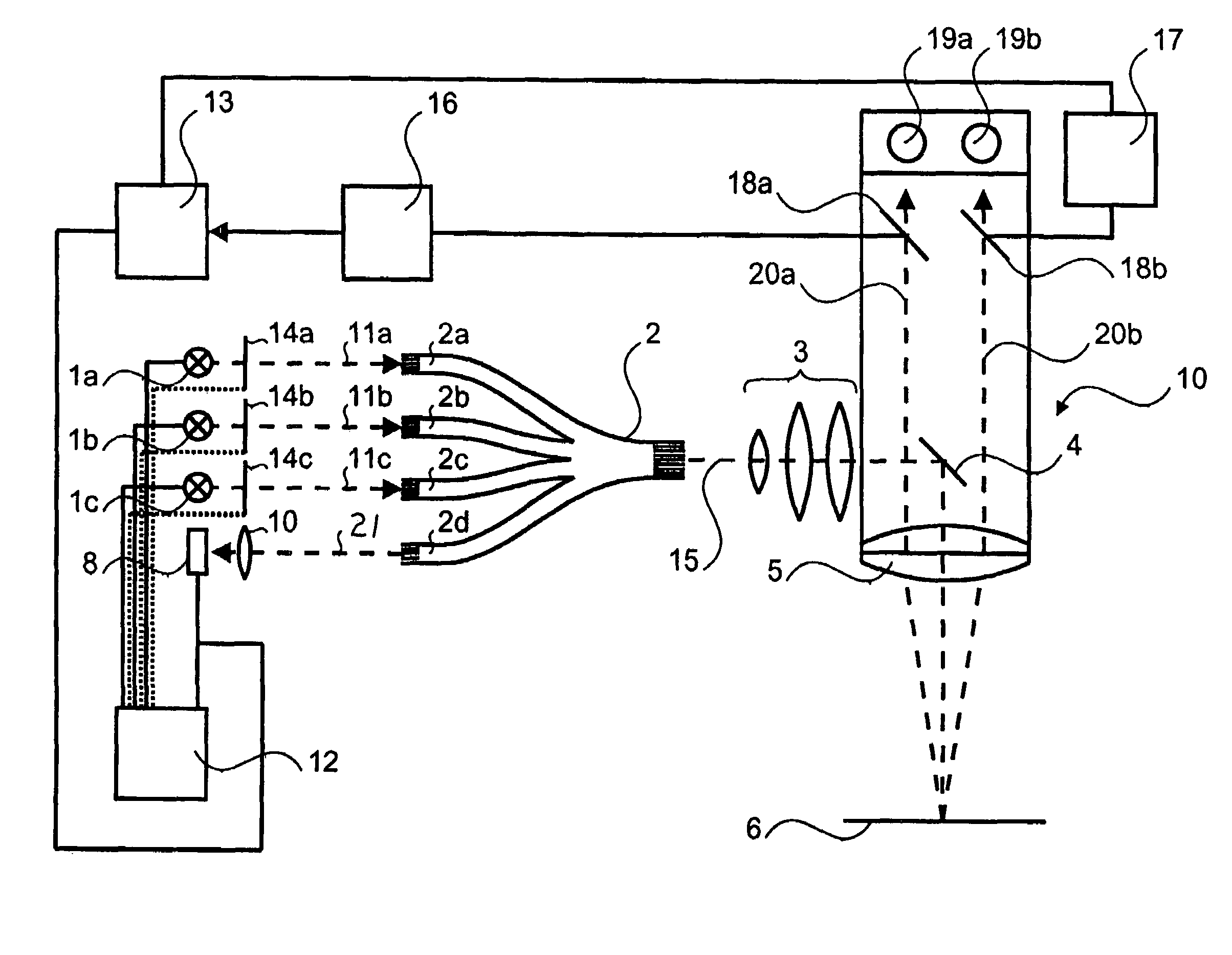
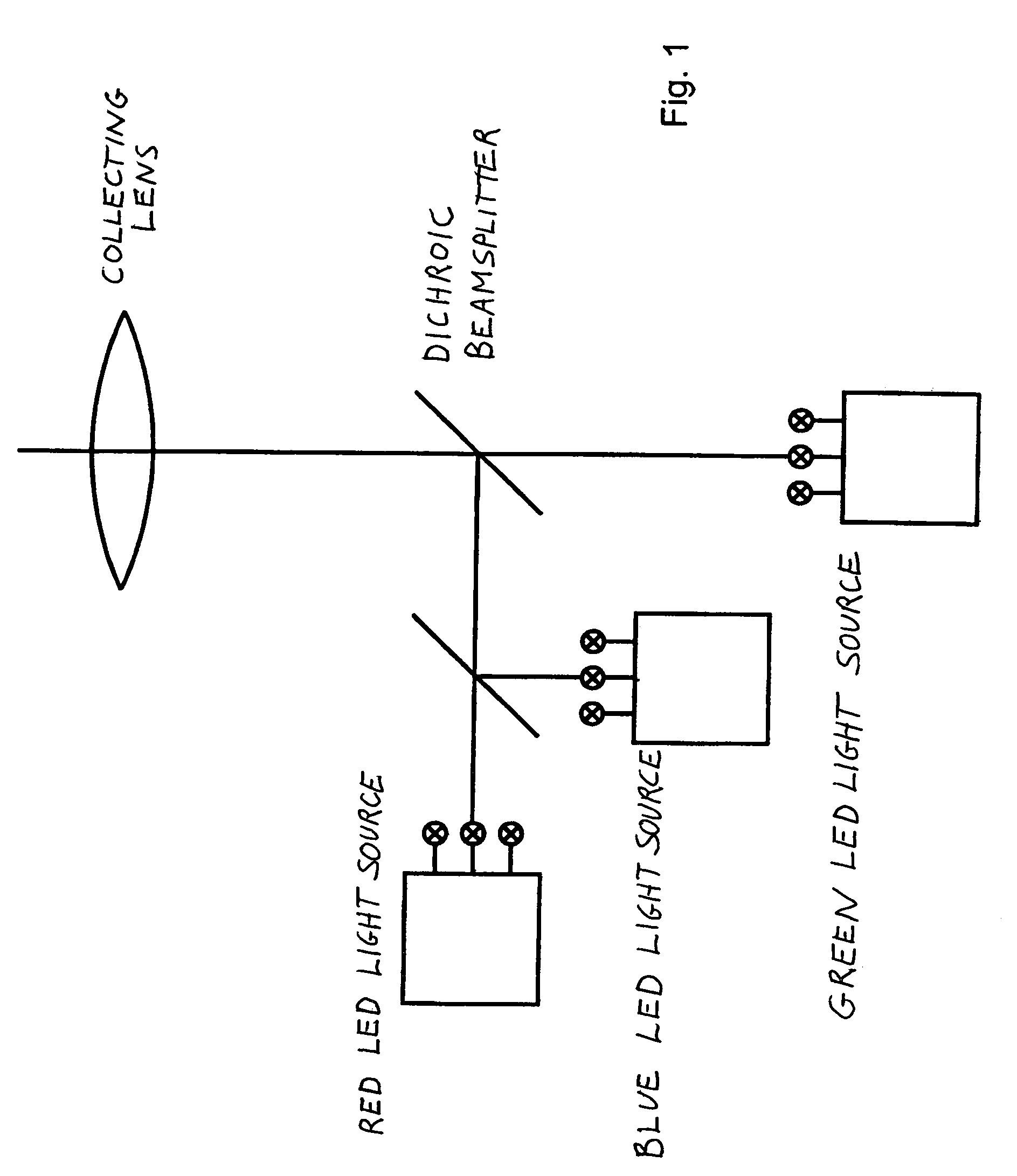
[0033]In FIG. 1, the light of a red, a green, and a blue planar LED light source is mixed into white light, in known fashion, using dichroic splitters.

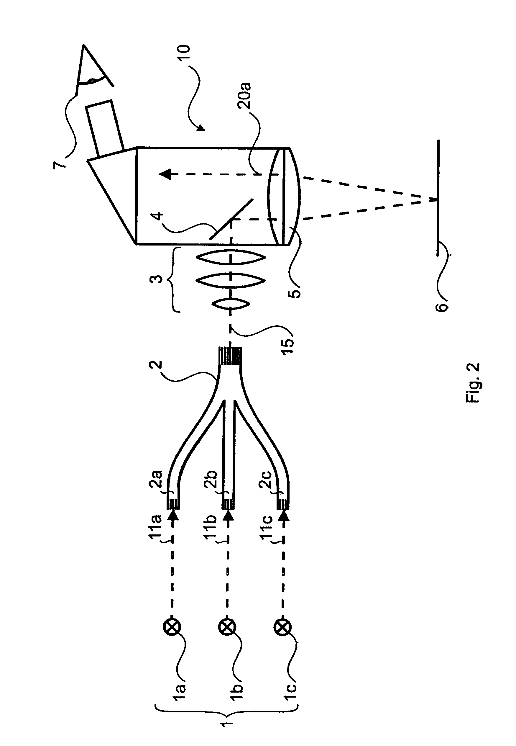
[0034]The illumination apparatus depicted in FIG. 2 encompasses at least one red-light-emitting LED 1a, one green-light-emitting LED 1b, and one blue-light-emitting LED 1c, which respectively emit red light 11a, green light 11b, and blue light 11c. This red-green-blue arrangement constitutes LED arrangement 1. Each of the light-emitting diodes 1a, 1b, 1c has associated with it one respective input of a total of three light guide arms 2a, 2b, 2c. The three light guide arms 2a, 2b, 2c come together and thus constitute a light guide with coupler 2 that has a single output. Here white mixed light 15 travels through an illuminating optical system 3 onto a mirror 4, by which it is directed through a main objective 5 of an optical observation device 10. Viewer 7 then sees the illuminated specimen 6 through observation beam path 20a.

[0035]Th...


PUM


Abstract

The invention concerns an illumination apparatus for an optical observation device (10), in particular a stereomicroscope or a stereo surgical microscope. A multi-armed light guide with coupler (2) mixes colored light emitted by light-emitting diodes (1a–c) to yield white mixed light (15).

Description

CROSS REFERENCE TO RELATED APPLICATIONS[0001]This application claims priority of the German patent application 103 39 618.7 filed Aug. 28, 2003 which is incorporated by reference herein.FIELD OF THE INVENTION[0002]The invention concerns an illumination apparatus for an optical observation device, in particular a stereomicroscope or a stereo surgical microscope.BACKGROUND OF THE INVENTION[0003]Light-emitting diodes (LEDs) that emit colored light have now become so bright that they are used, for example, for traffic signal systems and in the rear lights of vehicles.[0004]For a microscope illumination system, white light is principally desirable. White-light-emitting LEDs already exist. These are not, however, bright enough for this application. A plurality of light-emitting diodes arranged next to one another and emitting red, green, and blue light can be used to generate white light.[0005]DE 37 34 691 C2 presents a solution making possible a variety of illumination types and an inten...

Claims


Application Information

Patent Timeline
Patent Type & Authority Patents(United States)
IPC IPC(8): F21V5/00G02B21/00G02B6/42G02B6/00G02B21/06
CPCG02B21/06G02B6/4298Y10S362/80Y10S362/804
Inventor SANDER, ULRICH
Owner LEICA INSTR SINGAPORE PTE
Why Eureka
Try Eureka