Infusion pump and method for use

a technology of infusion pump and pump body, which is applied in the direction of liquid/fluent solid measurement, process and machine control, instruments, etc., can solve the problems of undesirable administration of such probes, severe measurement restrictions, and prior art systems that have generally failed to produce accurate measurements in a simple, compact package, and achieves relatively simple components, small size, and light weight

Inactive Publication Date: 2006-07-13
TANDEM DIABETES CARE INC
View PDF21 Cites 64 Cited by
  • Summary
  • Abstract
  • Description
  • Claims
  • Application Information

AI Technical Summary

Benefits of technology

[0010] A system according to the invention provides a non-contact method of monitoring the change in a fluid volume over time through the application of the Ideal Gas Law to measure the volume of an adjacent gas cylinder. The inventive approach avoids the use of probes or sensors that come into direct contact with the fluid. The use of such probes is undesirable in the administration of biologically active substances, since they increase the risk of contamination of the sterile environment in which the fluid must be maintained. Maintaining a sterile environment thus places severe restrictions on the measurement. As a result of these restrictions, prior art systems have generally failed to produce accurate measurements in a simple, compact package. Various methods have been used to establish approximate flow rates based on a presumed reaction rate, but no measurement of actual flow rate is provided to correct for errors introduced by changes in environmental conditions. Devices providing indirect flow measurements have also been suggested, but fail to offer a solution that is simple, reliably accurate, and inexpensive.
[0017] Unlike prior art devices, the present invention can be used to determine the precise dispensed volume of medication at any point in time. The total amount of medication delivered and, therefore, the amount of medication still available in the third chamber can be determined at any point in time based on an integration of flow measurements made over time. Because the device has relatively few components, it can be made extremely small, light, and compact. Because the components used are relatively simple, the device can be made extremely reliable without loss of calibration over extended periods of use. Because no sensors, probes, or other hardware are attached to the chamber containing the delivered fluid, the device is well suited to medical applications where sterile environment is critical. Finally, because the electrical components are a microprocessor, solenoid valve, two pressure transducers, and, in some preferred embodiments, one or more temperature sensors, the power consumption is extremely small.

Problems solved by technology

The use of such probes is undesirable in the administration of biologically active substances, since they increase the risk of contamination of the sterile environment in which the fluid must be maintained.
Maintaining a sterile environment thus places severe restrictions on the measurement.
As a result of these restrictions, prior art systems have generally failed to produce accurate measurements in a simple, compact package.
Various methods have been used to establish approximate flow rates based on a presumed reaction rate, but no measurement of actual flow rate is provided to correct for errors introduced by changes in environmental conditions.
Devices providing indirect flow measurements have also been suggested, but fail to offer a solution that is simple, reliably accurate, and inexpensive.

Method used


Image

  • Infusion pump and method for use
  • Infusion pump and method for use
  • Infusion pump and method for use

Examples


Embodiment Construction

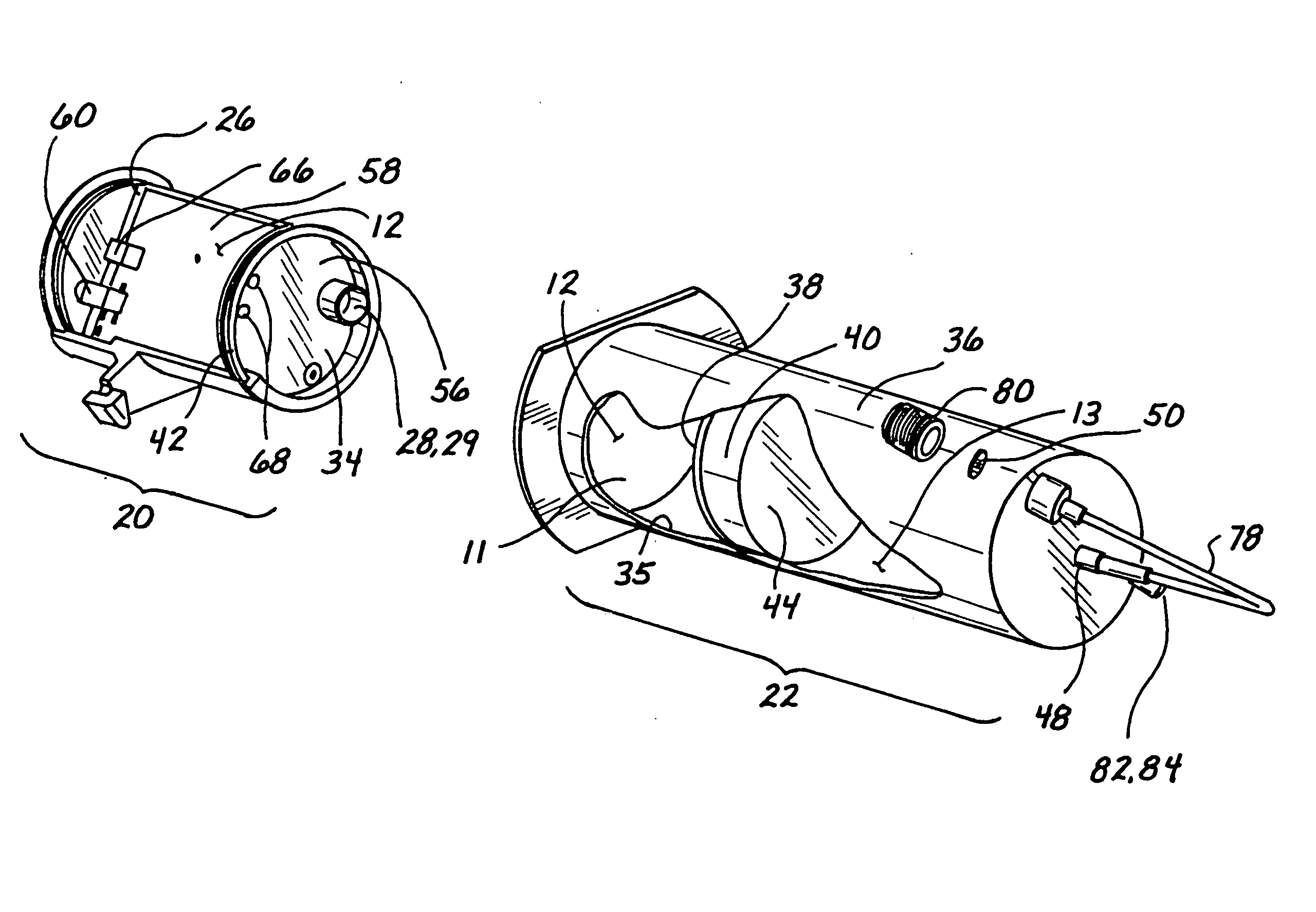
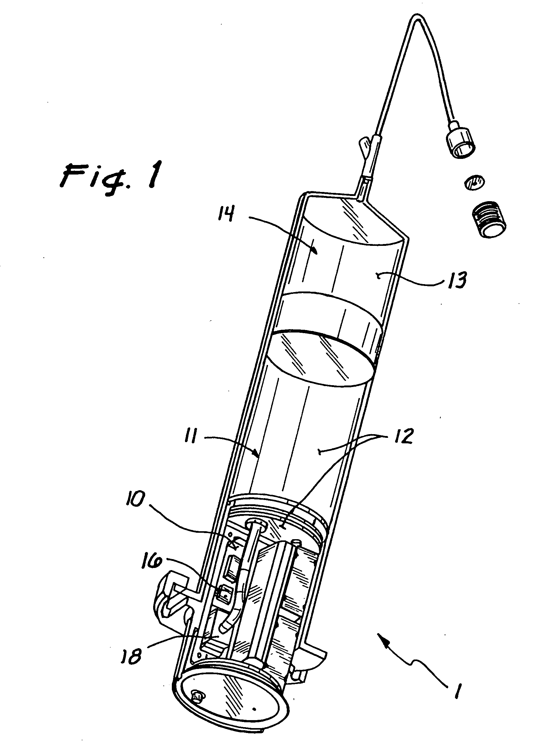
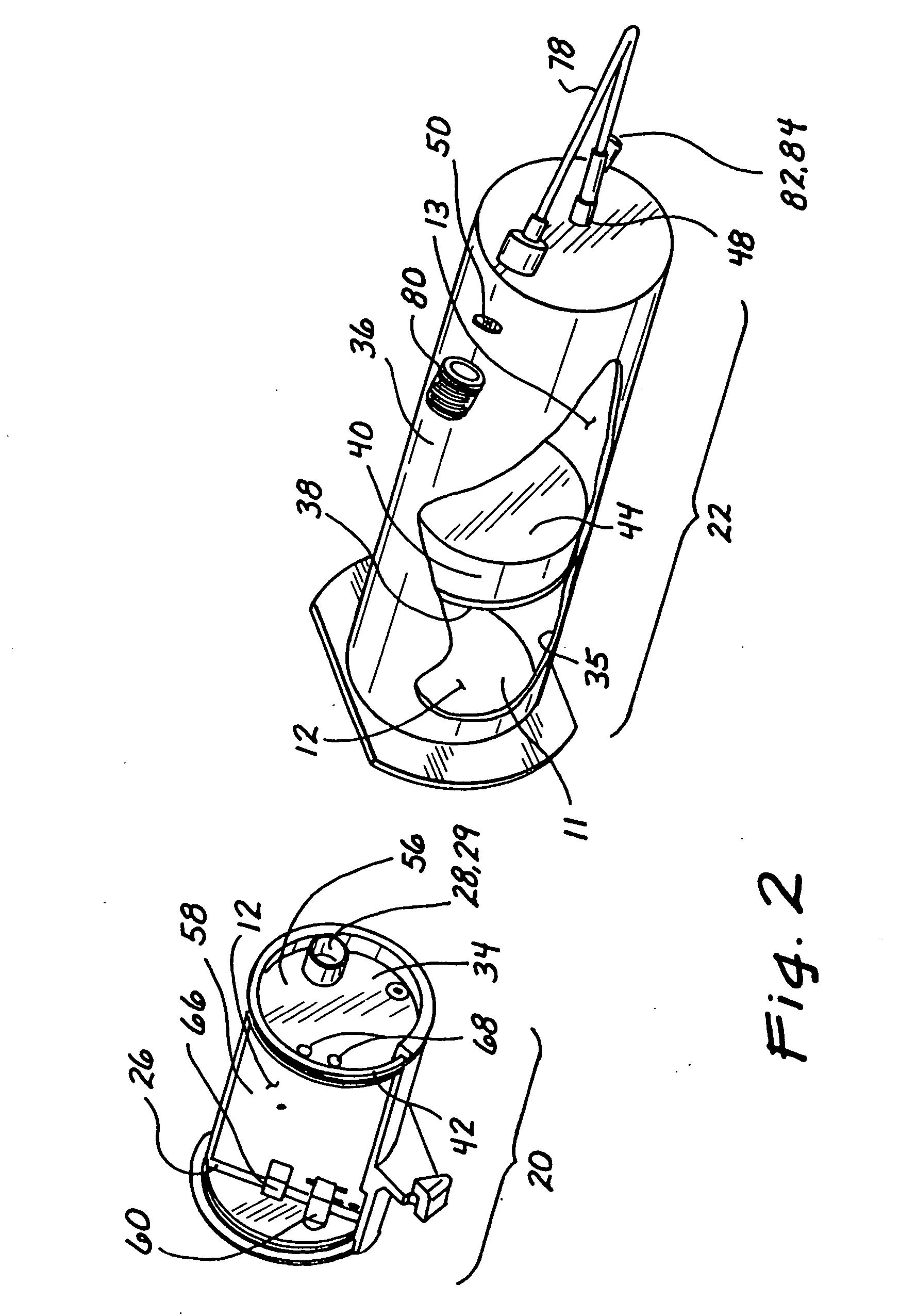
[0033] As shown in the drawings for purposes of illustration, the invention is embodied in a novel system to dispense a fluid and measure the fluid delivery rate.

[0034] In a preferred embodiment, shown in FIG. 1, the inventive device 1 comprises three chambers. A first chamber 10 and a second chamber 11 contain a gas 12 that is used to pump a fluid 13 contained in a third chamber 14. The fluid 13 is pumped at a controlled rate as the gas 12 in the first chamber 10 enters the second chamber 11. Two pressure probes 16 and 18 sense the pressure in the chambers 10 and 11. By monitoring these two pressures the volume of the second chamber 11 and, consequently, the volume of the third chamber 14 may be accurately determined. By knowing the volume of the third chamber 14, the volume or flow rate therefrom can be determined at any point in time. The resulting device provides a simple and economical method of delivering a fluid. Because the invention has few components, it is very reliable ...


PUM


Abstract

A fluid dispensing system provides a non-contact method of monitoring the change in the fluid volume over time. This approach avoids the use of probes or sensors that come into direct contact with the fluid to be dispensed. The system comprises an apparatus comprising three chambers. The first chamber has a fixed volume and contains a pressurized gas. A solenoid valve is used to control the flow of gas from the first chamber into the second. The second chamber is sealed so that the combined mass of air in the first and second chambers remains fixed. The third chamber is adjacent to the second and contains medication in the form of incompressible fluid that is to be administered to a human or animal subject via a suitable delivery port. A piston is disposed between the second and third chambers and is movable responsive to the flow of gas into the second chamber to dispense fluid from the third chamber as desired. By sensing the pressure in the first and second chambers at any point in time, a processor is programmed to calculate the flow rate or dispensed volume of the fluid being delivered using principles derived from the Ideal Gas Law.

Description

BACKGROUND [0001] This invention relates to an apparatus and associated methods for dispensing fluids at a known, measurable rate. More specifically, the present invention pertains to a pump for the intravenous infusion of a medical treatment fluid in which the delivery rate is determined without direct measurement of the fluid flow rate, by using sensed pressure values and the principle of conservation of mass. [0002] Drug delivery devices of varying construction are used to infuse medications or other biologically active substances into human or animal subjects. As used herein, the term “biologically active substance” means all types of medical and biological fluid used in the treatment of humans and animals including but not limited to peptides (such as insulin), analgesics, antiarrhythmics, steroids, hormones, nicotine, vitamins, anti-migraine medicine, anti-coagulants, local anesthetics, vaccines, allergens, muscle relaxants, etc. It should also be recognized that the apparatus...

Claims


Application Information

Patent Timeline
Patent Type & Authority Applications(United States)
IPC IPC(8): G01F1/34A61MA61M5/142A61M5/145A61M5/168A61M37/00G01F11/04
CPCA61M5/142A61M5/145A61M5/14593A61M5/16809G01F1/34G01F11/04Y10T137/85986Y10T137/0318
Inventor MALLETT, SCOTT
Owner TANDEM DIABETES CARE INC
Why Eureka
Try Eureka