Electronics module retention system

a technology of electronic modules and storage systems, applied in the direction of electrical apparatus casings/cabinets/drawers, coupling device connections, transportation and packaging, etc., can solve the problems of large enclosures and system footprints, and many mechanical storage systems occupy valuable spa

Active Publication Date: 2007-06-12
EMERSON AUTOMATION SOLUTIONS MEASUREMENT SYST & SERVICES LLC
View PDF10 Cites 41 Cited by
  • Summary
  • Abstract
  • Description
  • Claims
  • Application Information

AI Technical Summary

Problems solved by technology

Many mechanical retention systems also take up valuable space within the flow computer housing, both for the retention system and for the spa

Method used


Image

  • Electronics module retention system
  • Electronics module retention system
  • Electronics module retention system

Examples


Embodiment Construction

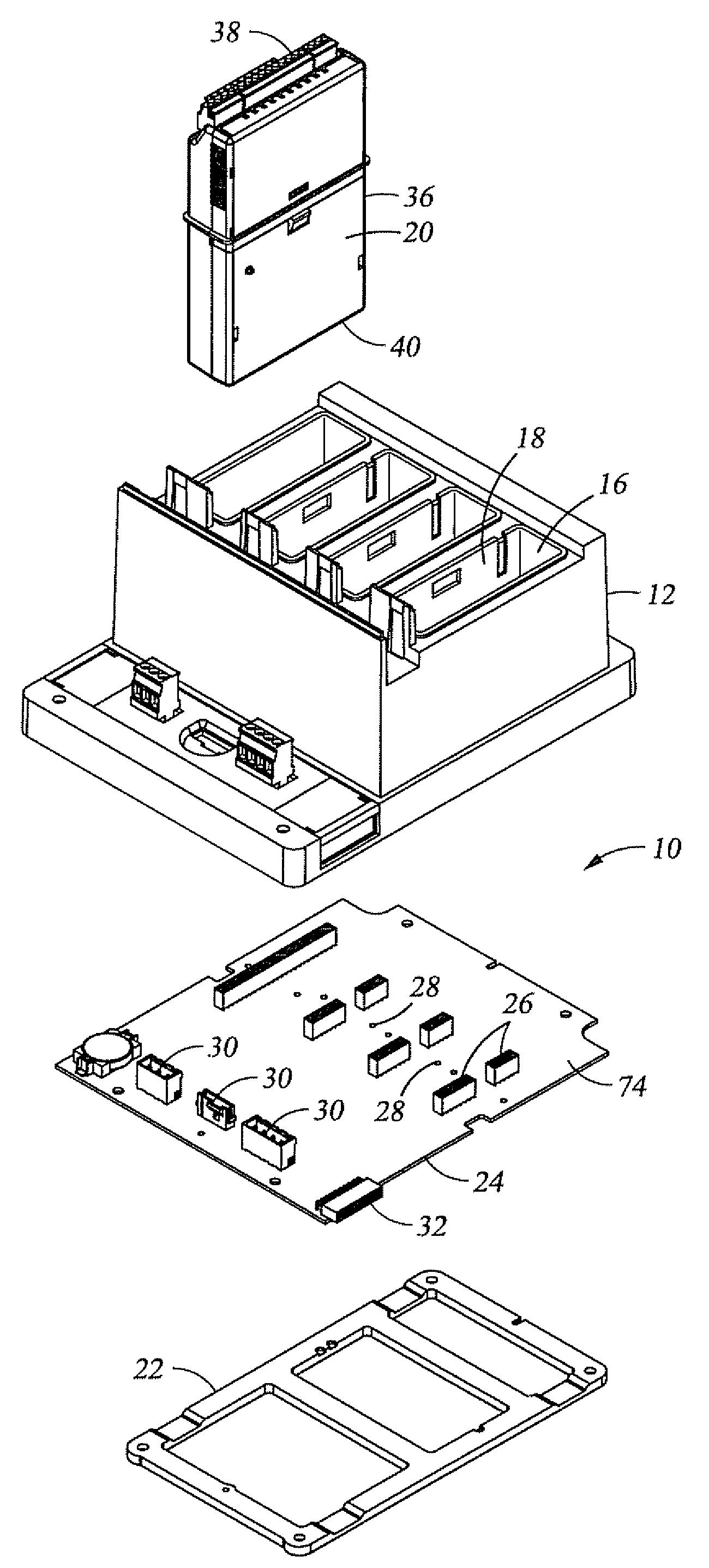
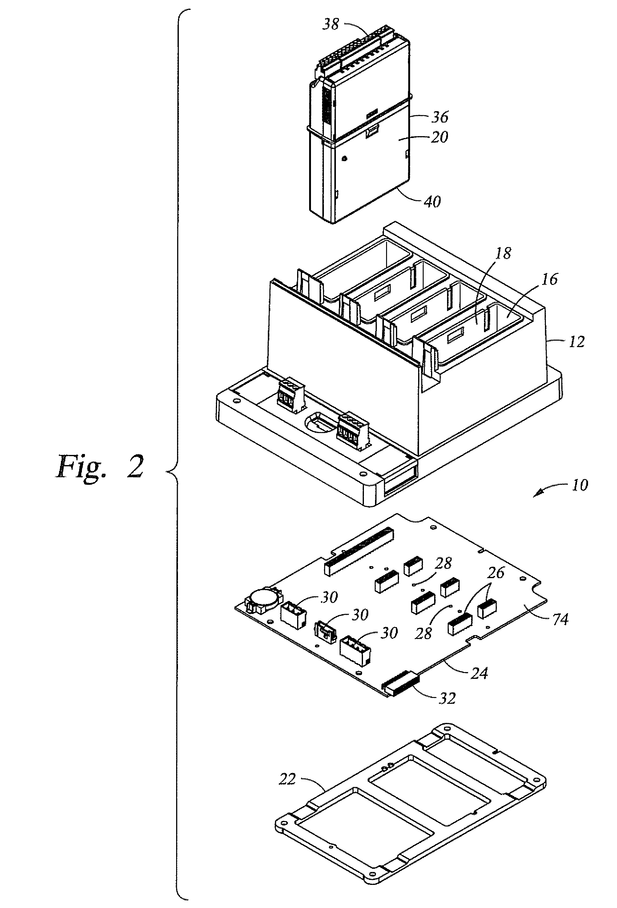
[0007]Embodiments of the present invention include an electronics module comprising an electronics assembly comprising a first connector and a second connector. The first and second connectors are disposed on opposite ends of the electronics assembly. A case encloses the electronics assembly. The first connector is accessible through a first side of the case and the second connector is accessible through a second side of the case. A locking tab is disposed on the case and is biased to an extended position. A sliding member is slidably coupled to the case and operable to move the locking tab to a retracted position.

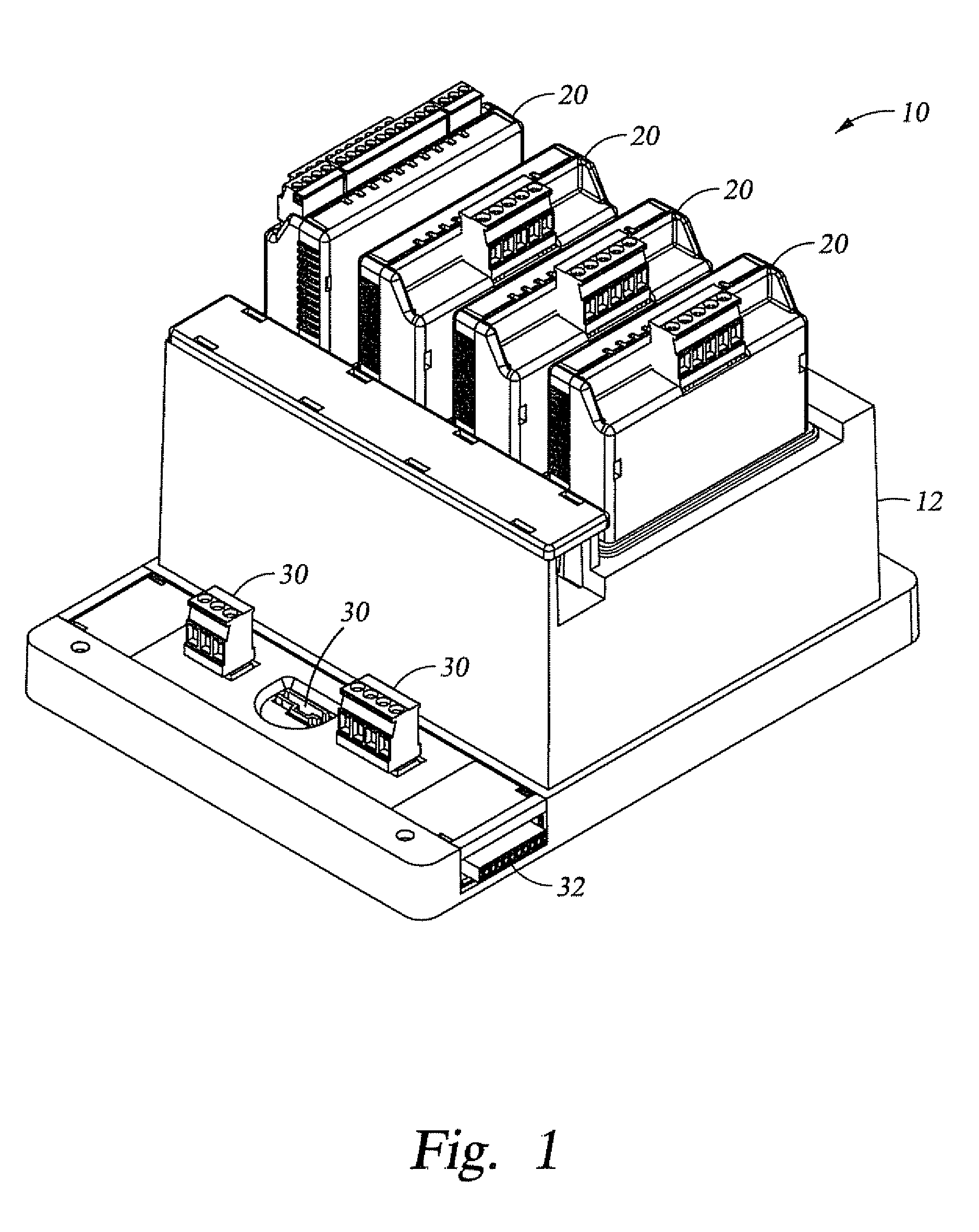
[0008]Other embodiments comprise an electronics block assembly comprising a backplane disposed within a housing. A sleeve is disposed within a receptacle in the housing. An electronics module is enclosed within a case that is insertable into the sleeve. A locking tab is disposed on the case and is biased to an extended position where the locking tab is engaged with the sle...


PUM


Abstract

An electronics module comprises an electronics assembly having a first connector and a second connector. The first and second connectors are disposed on opposite ends of the electronics assembly. A case encloses the electronics assembly. The first connector is accessible through a first side of the case and the second connector is accessible through a second side of the case. A locking tab is disposed on the case and is biased to an extended position. A sliding member is slidably coupled to the case and is operable to move the locking tab to a retracted position.

Description

CROSS-REFERENCE TO RELATED APPLICATIONS[0001]Not applicable.STATEMENT REGARDING FEDERALLY SPONSORED RESEARCH OR DEVELOPMENT[0002]Not applicable.BACKGROUND OF THE INVENTION[0003]The invention relates to methods and apparatus for retaining sub-components within an assembly. More specifically, embodiments of the invention are related to systems and apparatus for simplifying the installation and removal of an electronics assembly into a housing.[0004]In oil and gas applications, flow computers are used for high-performance measurement and control functions, such as fiscal metering, custody transfer, batch loading, meter proving, multi-stream measurement, station monitoring / control and other applications. In order to provide flexible configurations and simplify maintenance, many of these flow computers utilize separate electronics modules to perform individual functions. Because a particular flow computer may only perform a limited number of functions, only those modules required to perf...

Claims


Application Information

Patent Timeline
IPC IPC(8): H05K7/10H05K7/12
CPCB60R16/0239H01R13/518H05K7/1405H05K7/1474H05K7/1477
Inventor SICKELS, DENNIS GENE
Owner EMERSON AUTOMATION SOLUTIONS MEASUREMENT SYST & SERVICES LLC
Why Eureka
Try Eureka