Data processing apparatus having error concealment function

Inactive Publication Date: 2007-06-12
SONY CORP
View PDF12 Cites 4 Cited by
  • Summary
  • Abstract
  • Description
  • Claims
  • Application Information

AI Technical Summary

Benefits of technology

[0016]It is therefore an object of the present

Problems solved by technology

However, as compared with audio data and text data, video data are huge in data volume, so that the processing of video data requires significantly much heavier load than that in the processing of audio data and text data, despite of the rapid enhancement in the recording rate of recording media.
However, if video data is compressed by the MPEG encoding for example, the decoding of compressed video data sometimes takes much time.
Because MPEG is required to decode another frame in order to decode a certain frame as described above, it is difficult to cope with errors, if any, in the data read from an optical disk, namely it is difficult to execute error concealment.
Therefore, if the I-picture forming a GOP cannot be decoded due to an error, all frames of that GOP and some of the frames of the next GOP may not be decoded.
For this reason, when video data is encoded by MPEG and recorded to an optical disk, counter error measures such as enhancing error correction capabilities may be taken; however, it is still difficult for this approach to perform high redundant, complete error correction.
However, if an error occurs on the video data recorded in a particular recording area and the video data recorded in another recording area are read in replacement, a seek time, a rotational delay time, and a time for reading the video data are required, thereby making it difficult to reproduce the video data real-time.
However, in this method, if an error occurs, a circuit dedicated to video data interpolation, namely a circuit dedicated to error concealment, is required, thereby enlarging equipment scale.
In addition, this method involves the degradation in compression efficiency because pixels and blocks in a spatial or temporal proximity with each other are recorded to discontinuous positions on an optical disk.

Method used


Image

  • Data processing apparatus having error concealment function
  • Data processing apparatus having error concealment function
  • Data processing apparatus having error concealment function

Examples


Embodiment Construction

[0031]This invention will be described in further detail by way of example with reference to the accompanying drawings.

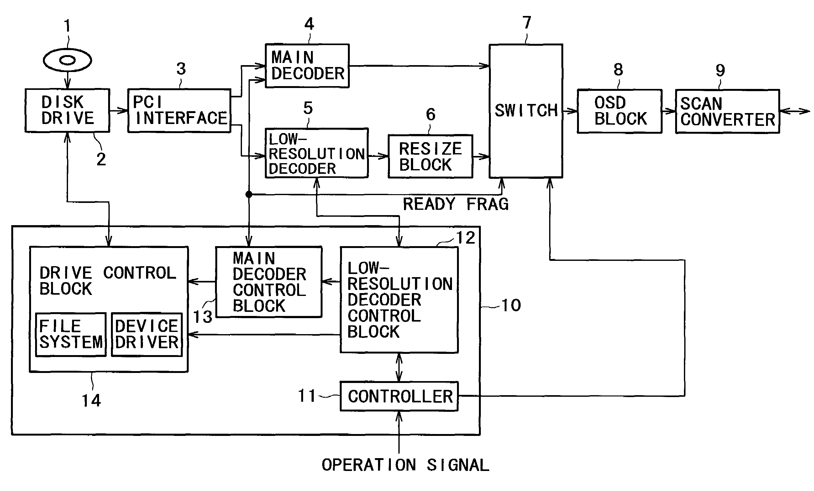
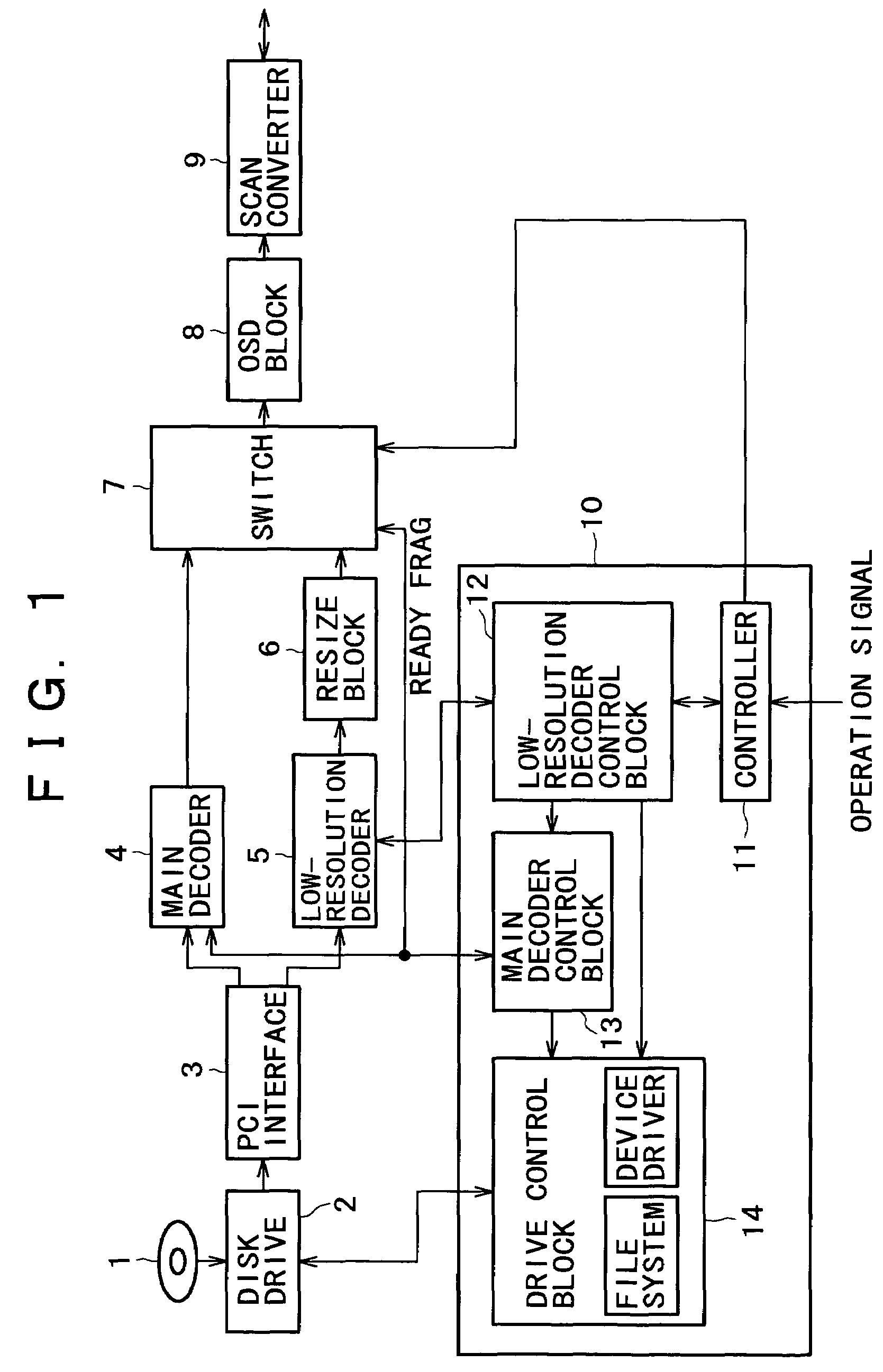
[0032]Now referring to FIG. 1, there is shown an exemplary configuration of a disk reproducing apparatus practiced as one embodiment of the invention.

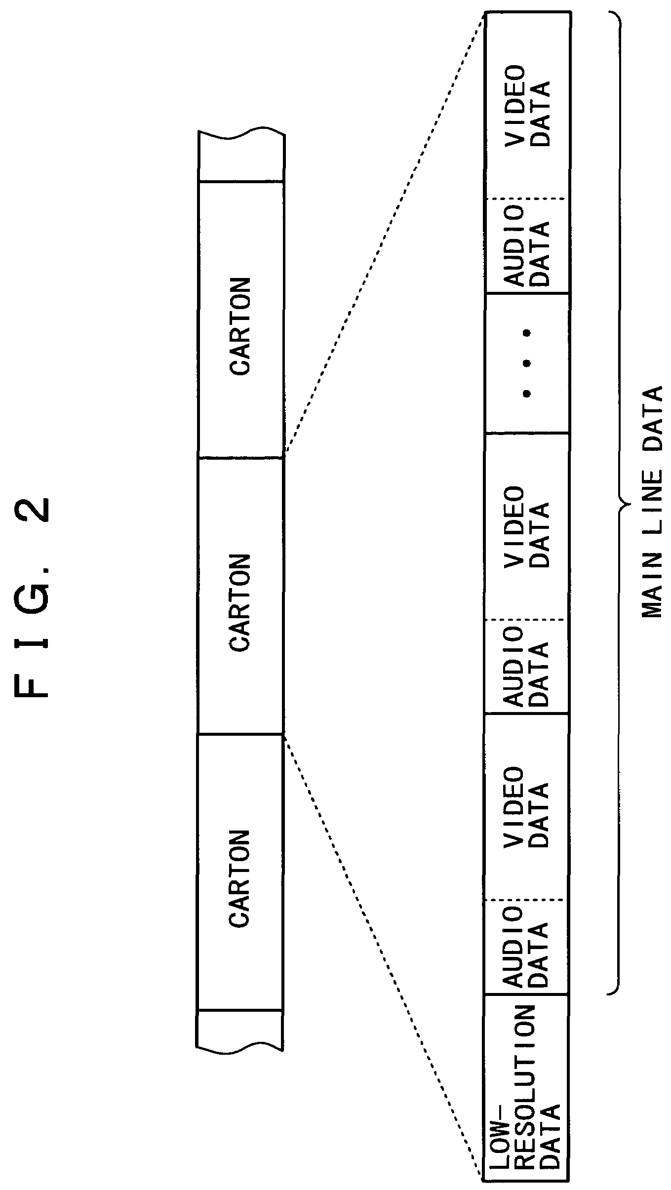
[0033]On an optical disk 1, encoded data obtained by MPEG-encoding, for example, video data of high resolution or standard resolution is recorded. In addition, encoded data obtained by encoding, based on a predetermined method, video data smaller in amount than the video data having high or standard resolution, namely, for example, video data having low resolution, which is the video data obtained by lowering the resolution of the encoded data, is recorded on the optical disk 1.

[0034]The video data having high or standard resolution is originally intended for the provision to the user. The encoded data obtained by encoding the video data is hereafter appropriately referred to as main line data. The video data of low re...


PUM


Abstract

Main line data as video data and low-resolution data obtained by lowering the resolution of the video data and the data amount thereof is recorded on an optical disk. The main line data and the low-resolution data are read from the optical disk. While the main line data and the low-resolution data are decoded, the main line data is detected for an error. If the main line data is found not having an error, then the decode result of the main line data is outputted. If the main line data is found having an error, then the decode result of the low-resolution data is outputted.

Description

BACKGROUND OF THE INVENTION[0001]The present invention relates generally to a data processing apparatus for facilitating data error concealment.[0002]Recently, recording media significantly enhanced in recording rate, such as optical disks and so on, are in practical use, realizing the long-time recording of video data with comparatively high picture quality.[0003]However, as compared with audio data and text data, video data are huge in data volume, so that the processing of video data requires significantly much heavier load than that in the processing of audio data and text data, despite of the rapid enhancement in the recording rate of recording media.[0004]In order to reduce the recording rate while restricting picture quality deterioration, a method is known in which video data is compressed by means of MPEG (Moving Picture Experts Group) encoding for example.[0005]However, if video data is compressed by the MPEG encoding for example, the decoding of compressed video data some...

Claims


Application Information

Patent Timeline
IPC IPC(8): G06F11/00H04N5/92G11B20/12G11B20/18H02H3/05H04N5/85H04N9/79H04N9/804H04N9/82H04N19/00H04N19/102H04N19/166H04N19/189H04N19/423H04N19/44H04N19/65H04N19/67H04N19/85H04N19/89
CPCH04N9/7921H04N5/85H04N9/8042H04N9/8227
Inventor KAWAHARA, MINORU
Owner SONY CORP
Why Eureka
Try Eureka