Speed limiting for rotary driven sprinkler

a technology of rotary drive and speed limit, which is applied in watering devices, horticulture, agriculture, etc., can solve the problems of speed limit, speed limit, and speed limit provided by the turbine, and achieve the effect of little or no speed limit and turbine speed limi

Inactive Publication Date: 2007-06-19
KAH JR CARL L
View PDF26 Cites 24 Cited by
  • Summary
  • Abstract
  • Description
  • Claims
  • Application Information

AI Technical Summary

Benefits of technology

[0015]The present invention meets the above-described need by applying dynamic viscous braking to the power train which couples the turbine output shaft to the sprinkler head. This can provide turbine speed limiting whe

Problems solved by technology

Speed limiting is also provided if the sprinkler overspeeds due to a blocked by-pass flow valve, or other malfunction.
Since the damping effect is speed related, t

Method used


Image

  • Speed limiting for rotary driven sprinkler
  • Speed limiting for rotary driven sprinkler
  • Speed limiting for rotary driven sprinkler

Examples


Embodiment Construction

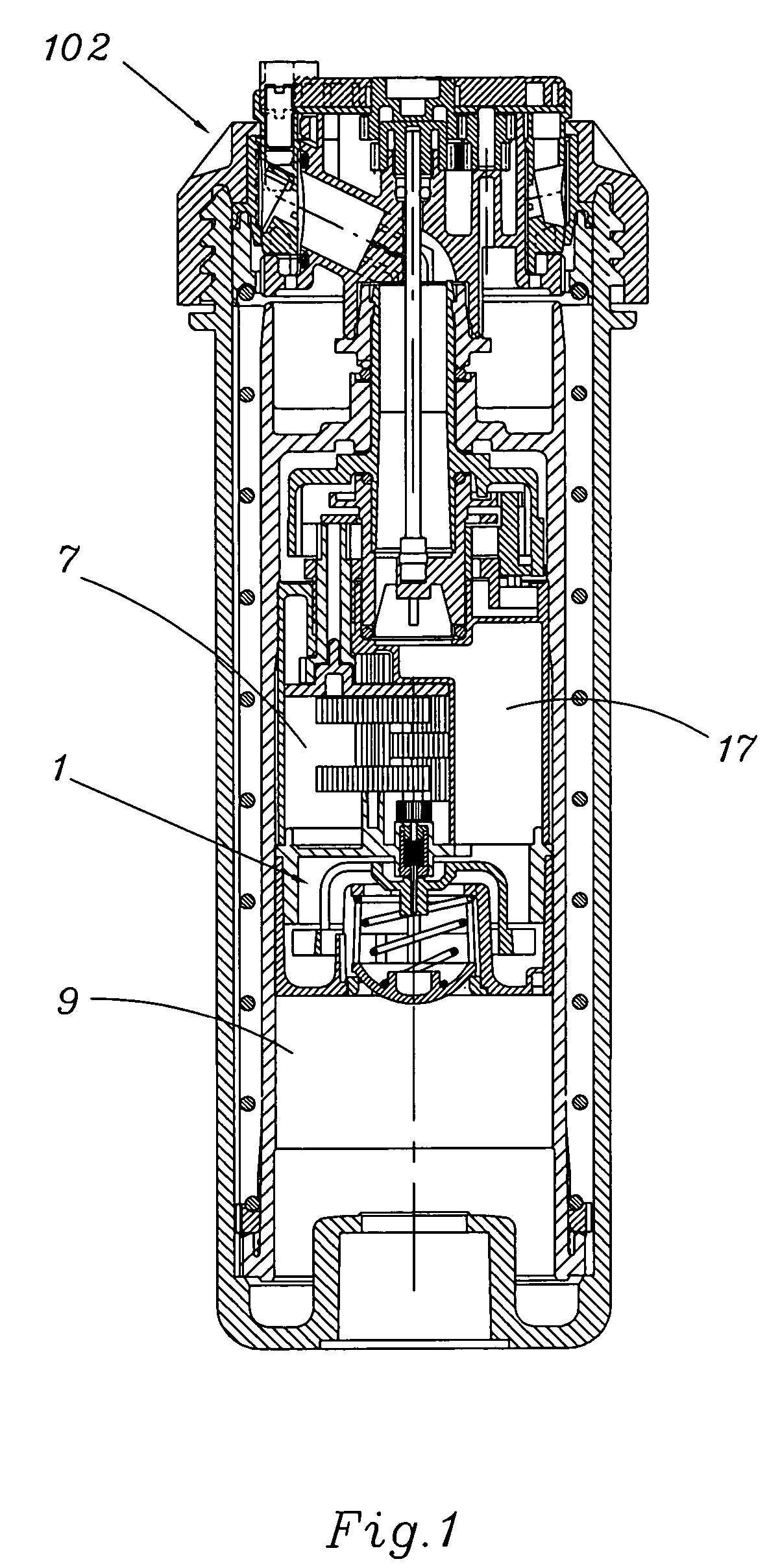
[0035]FIG. 1 shows in cross section, generally denoted at 100, a water turbine driven sprinkler such as described in detail in my U.S. Pat. Re. 35,037, the entire disclosure of which is incorporated herein by reference as if fully set forth.

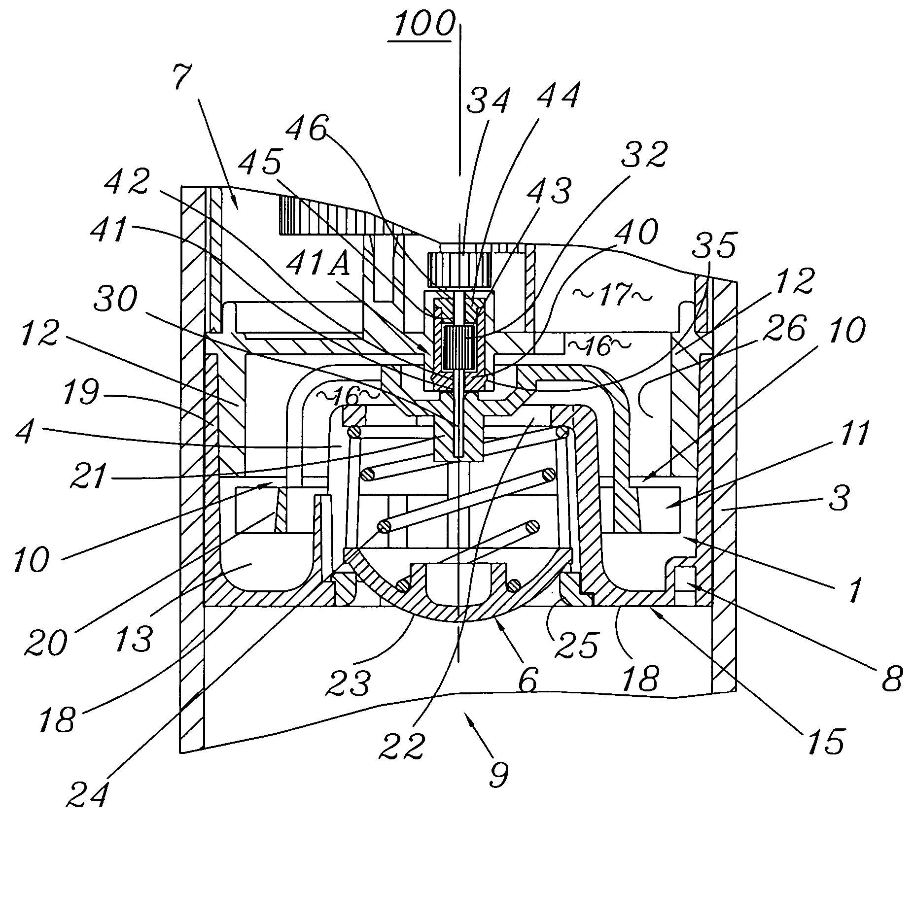
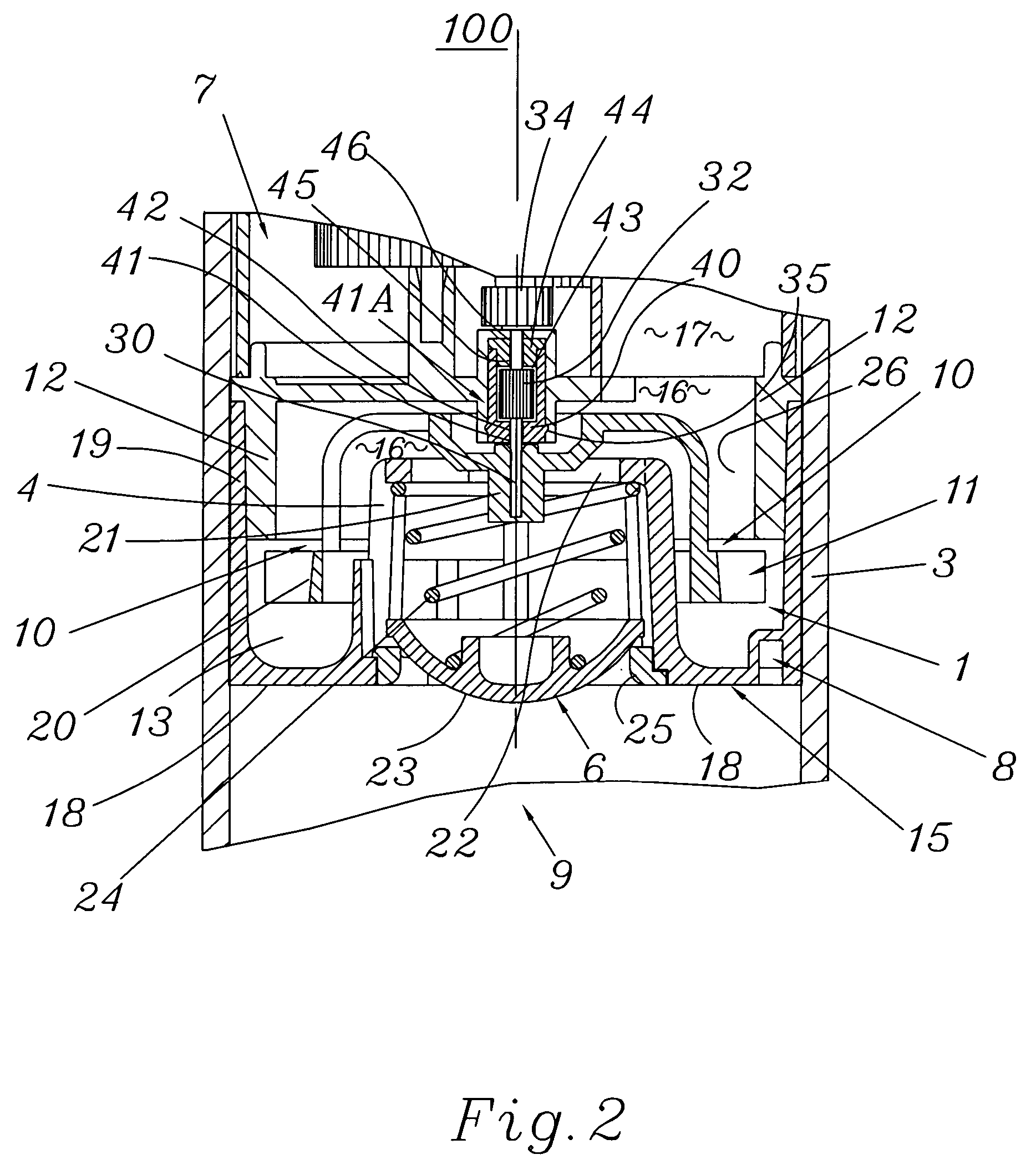
[0036]FIGS. 2 and 3 illustrate a turbine assembly, generally denoted at 1, for sprinkler 100 which incorporates a first embodiment of the invention. Referring to FIGS. 1-3, turbine assembly 1 is mounted in a housing 3, and, by way of an output shaft 30 and a gear 34, drives a gearbox 7, which rotates or oscillates a sprinkler head 102 in any conventional or desired manner. As will be understood, water (or during winterization, compressed air) entering turbine assembly 1 from below at 9 drives the turbine, and thereafter flows through an outlet passage 17 to the sprinkler head.

[0037]The turbine itself is comprised of a rotor 11 located in a rotor chamber 13 formed by a stator cover assembly 15 positioned on the upstream side of the turbine, and by...


PUM


Abstract

A speed limiting mechanisms for turbine-driven fluid distribution apparatus usable with compressible fluid such as compressed air and incompressible fluid such as water. Dynamic viscous damping of the turbine output power train is used to control the rotational speed of the turbine. This prevents overspeeding when the turbine is air driven, and also when the turbine is water driven, under abnormal conditions such as blockage of a bypass area designed to control the turbine speed by limiting flow to the turbine. The same mechanism can be used to impose a lower rotational speed in the turbine during normal operation in conjunction with a turbine optimized for lower speed operation to reduce the required gear reduction in the power train.

Description

CROSS-REFERENCE TO RELATED APPLICATIONS[0001]This application is based on and claims priority to U.S. Provisional Application 60 / 446,171, filed Feb. 7, 2003, the entire disclosure of which is incorporated herein by reference.[0002]This application is also related to my U.S. patent application Ser. No. 10 / 141,261, filed May 7, 2002, entitled SPEED LIMITING TURBINE FOR ROTARY DRIVEN SPRINKLER, the entire disclosure of which is also incorporated herein by reference.BACKGROUND OF THE INVENTION[0003]1. Technical Field of the Invention[0004]The present invention relates to speed limiting for a water turbine or other water motor driven sprinklers, and more particularly, to a method and apparatus which employs dynamic viscous braking to control the water motor output shaft speed in an improved, convenient and reliable manner. By employment of the invention, a sprinkler system can be winterized by purging water from the system using high pressure air, without the risk of damage to the rotati...

Claims


Application Information

Patent Timeline
IPC IPC(8): B05B17/00A01GB05B3/00B05B3/04
CPCB05B3/005B05B3/0422
Inventor KAH, JR., CARL L
Owner KAH JR CARL L
Why Eureka
Try Eureka