Speed control mechanism

Inactive Publication Date: 2006-05-18
AQUATIC DEV GROUP
View PDF17 Cites 1 Cited by
  • Summary
  • Abstract
  • Description
  • Claims
  • Application Information

AI Technical Summary

Benefits of technology

[0007] The shortcomings of the prior art are alleviated by using the speed control mechanism constructed in accordance with one or more aspects of the present invention. Generally described, a speed control mechani

Problems solved by technology

Rear wheels are not provided for conventional sleds used on higher pitched tracks because the sled would gain too much speed.
Therefore, a sled with rear wheels is more stable and less susceptible to accidents, but not usable on a higher pitch tracks because it causes the sled to travel too fast.
As expected, some riders drive too fast down the track, which sometimes results in acciden

Method used


Image

  • Speed control mechanism
  • Speed control mechanism
  • Speed control mechanism

Examples


Embodiment Construction

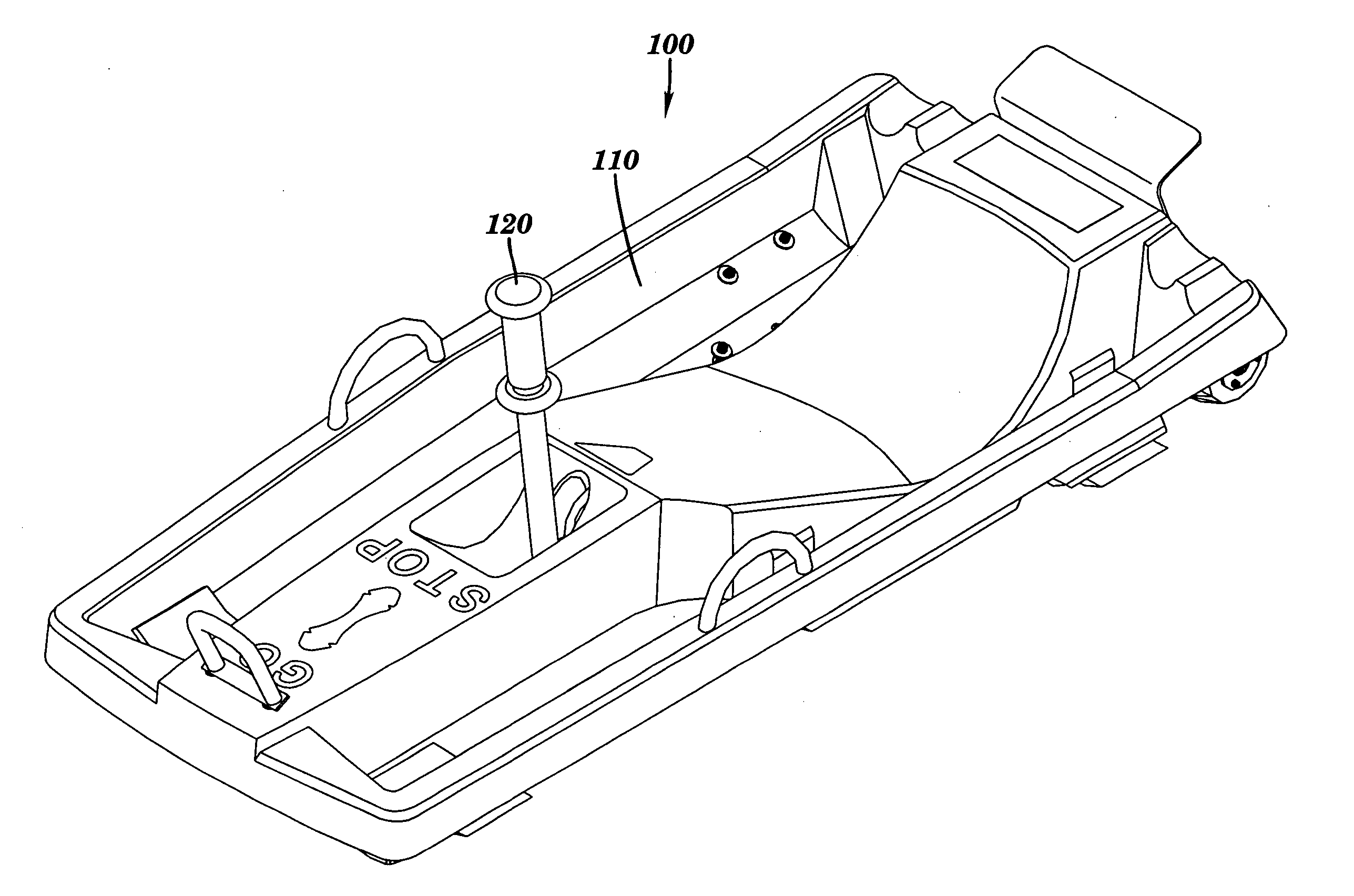
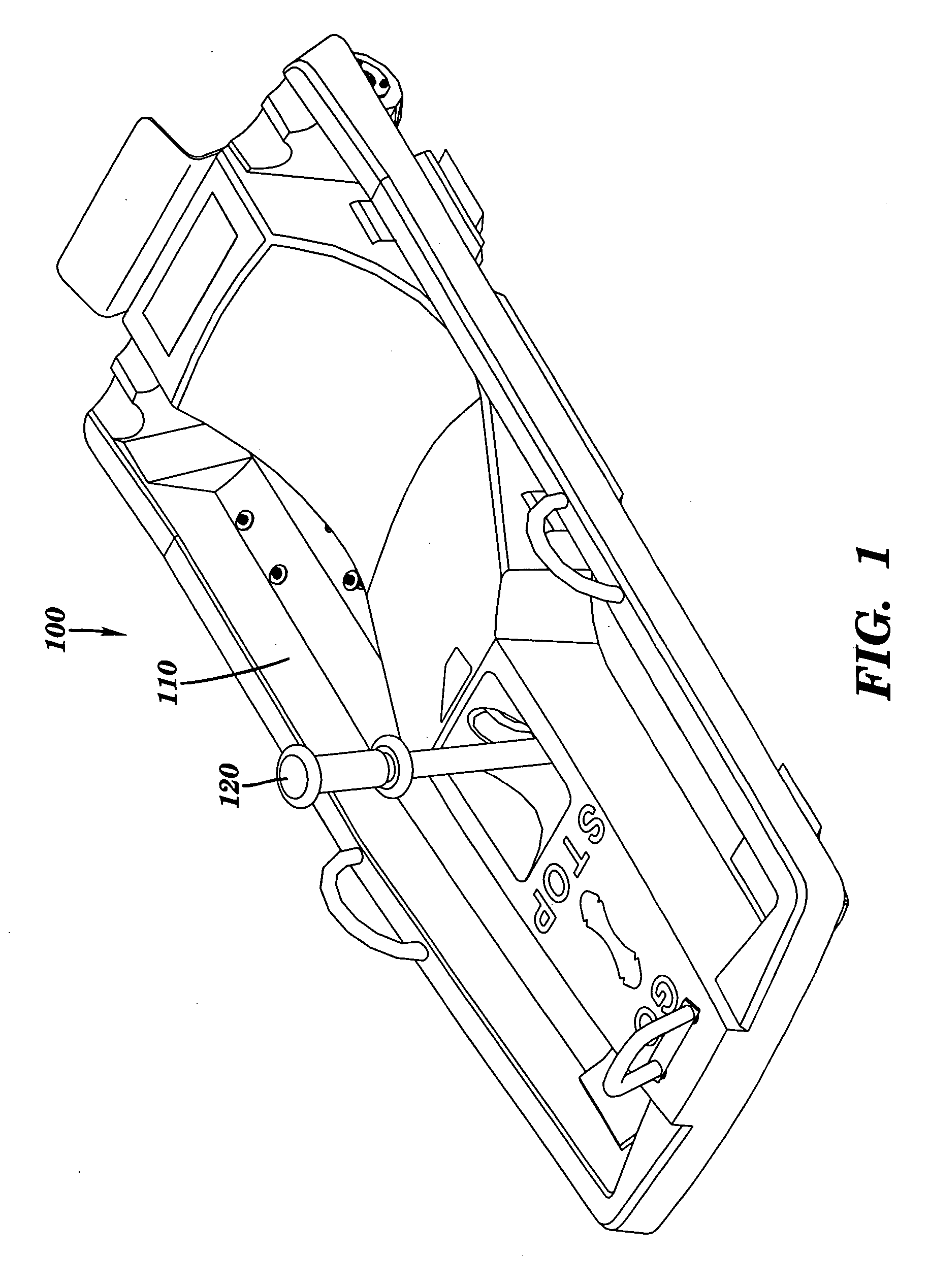
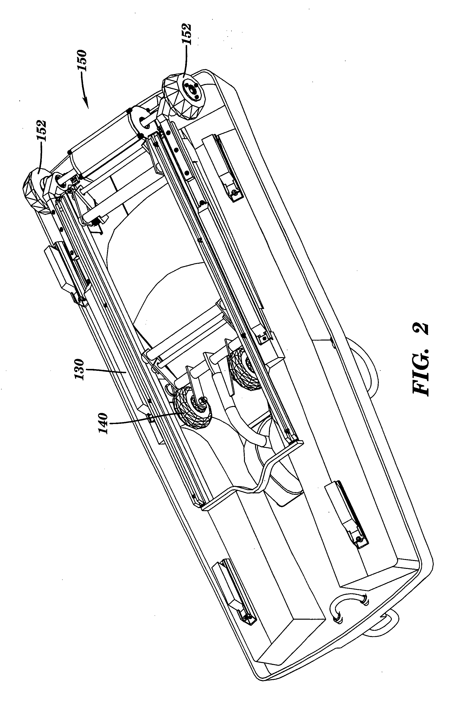
[0027] In one aspect of the present invention there is provided a hydraulic speed restrictor attached to a rear axle assembly of a gravity driven vehicle to allow for more stable, safer and enjoyable rides. For the purpose of convenience only, the speed restrictor will be described in reference to an alpine sled, but it should be understood that the speed restrictor can also be used on other gravity driven vehicles that require control of speed down high pitched terrain, such as, for example, soap box cars, bobsleds, racing carts and the like. Also, it is understood that the speed restrictor can also be applied to a front axle assembly or one or more axle assemblies of a gravity driven vehicle.

[0028]FIGS. 1 and 2 illustrate the top and undercarriage, respectively, of one example of an alpine sled 100 that can be adapted to incorporate a speed restrictor constructed in accordance with one or more aspects of the present invention. Alpine sled 100 includes a chassis 110 for supporting...


PUM


Abstract

A speed restrictor for a gravity driven vehicle is provided. The speed restrictor is configured to limit the speed of the gravity driven vehicle by restricting rotation of a wheel axle while the gravity driven vehicle descends down a mountain track.

Description

CROSS REFERENCE TO RELATED APPLICATIONS [0001] This application is a Non-provisional of U.S. Provisional Application Ser. No. 60 / 627,723, filed on Nov. 12, 2004 and U.S. Provisional Application Ser. No. 60 / 650,472, filed on Feb. 7, 2005, the entire disclosures of which are incorporated herein by reference.FIELD OF INVENTION [0002] This invention relates generally to a speed control mechanism and, more particularly, to a speed restrictor for a gravity driven vehicle, such as, for example, an alpine sled, bobsled, soap box car, racing cart and the like. BACKGROUND OF THE INVENTION [0003] During the summer, ski resorts provide a ride down a mountain on a track using a sled. The track typically consists of an assembly of prefabricated sections having a variety of different curves and straight sections. The track is designed and installed to conform to the terrain of the mountain and may vary from 1000 to 5000 feet in length depending on the vertical drop between the start and finish. Th...

Claims


Application Information

Patent Timeline
IPC IPC(8): B62M1/00
CPCB60T1/02B60T10/02B62B3/007B62B5/0069B62B5/04B62B15/008
Inventor ALBERTSSON, STIG
Owner AQUATIC DEV GROUP
Why Eureka
Try Eureka