Method For Evaluating, An Automation System And a Controller

Active Publication Date: 2008-12-25
ABB (SCHWEIZ) AG
View PDF20 Cites 5 Cited by
  • Summary
  • Abstract
  • Description
  • Claims
  • Application Information

AI Technical Summary

Benefits of technology

[0009]It is therefore an object of the present invention to provide a method for ensuring that a new version of an application to be installed is functioning, and importantly, functioning in a real environment and under actual conditions, resulting in a smooth and safe change-over from one version to another, thereby alleviating the shortcomings of the prior art.
[0011]A further yet object is to provide a way to assist an operator in minimizing the risks involved when making a change to a control program. This is accomplished by making the operator aware of differences between an existing and a new version of a control application, and also making the operator aware of potential step changes in process output possibly caused by the new version.
[0014]In accordance with the present invention a method for evaluating an application for controlling a process within an automation system is provided. Two or more versions of the application are stored within a controller, such as a process controller or a programmable logic controller. The method comprises the steps of inputting to all of the different versions of the application which versions reside within the same controller and of which one version is controlling said process, an input signal obtained from the process; executing, in the controller, the same tasks based on said input signal for the different versions of the application; generating a report comprising comparisons of the outputs from the different versions of the application; and evaluating, based on the generated report, the version(s) not used for controlling the process. In accordance with the invention, tasks are executed for all versions in the controller based on the same input signal, but only the output signal obtained from the version currently controlling the process is output as the required output for controlling the process, the output signals obtained from all other versions are made available for evaluation, for example by an operator. By means of the invention a new upgraded version of an application can be executed concurrently with a currently used version and evaluated under true production circumstances utilising real input signals, and thereby eliminating the risk of shutdowns of the production. Further, by means of the invention it is ensured that purposeful comparisons are made as well as enabling the user to evaluate a version being currently under development before using it for controlling the processes.
[0016]In accordance with yet another embodiment of the invention the execution of the tasks is performed in sequence for the different versions, or in an alternative embodiment in a quasi-parallel manner. This feature provides a flexible way to execute the tasks, both ways ensuring that the same tasks are performed for the different versions and thus ensuring that the comparisons being made are relevant.
[0017]In accordance with yet a further embodiment of the invention, the step of generating a report comprises comparing the outputs from all of the at least two versions and establishing differences between the outputs. A user is thereby able to easily compare the different versions.
[0018]In accordance with another embodiment of the invention, the method further comprises the step of presenting found differences to a user. This facilitates the evaluation and such presentation can be accomplished in any desired manner, such as for example in the form of graphs, numbers or diagrams.

Problems solved by technology

These circumstances bring about the drawback that shutting down one process section quickly causes other shut downs of other process sections located up- and downstream and eventually a shut down of the whole plant.
Starting up a plant is generally a time-consuming process, often requiring several hours or even days.
A stop in one section thus causes production losses, which can be in the multimillion-dollar range.
Further, a stop and restart also causes excessive wear on process equipment and catalysts.
This in turn entails maintenance work more frequently, servicing and catalyst replacement, thus adding to the long-term cost of operation.
In view of the high costs associated with a production stop such changes of the control programs are normally performed on-line, but to make a change on-line entails a risk of upsetting the process being changed and care has to be taken when upgrading the process applications.
This can bring about serious problems should the new version not be adequately downloaded, if the new version contains bugs or if it is non-functioning or if it contains unforeseeable incompatibilities with the system, for example leading to disturbances or instabilities in the controlled process.
As mentioned, such interruptions in production are very expensive, or could even, depending on the industry in question, be dangerous.
It is difficult to foresee whether a new version of a control application would be functioning in a real environment, and if it is not functioning, it is very difficult to know which part of the application is not functioning satisfactory.
A difficulty of this state of the art solution is that it requires two controllers, which increases the cost.
A further difficulty is that it requires some kind of synchronization and arbitration mechanism between the two controllers, in order to synchronize execution cycles, arbitrate between the process outputs from the two controllers, determine any differences in results and generate a difference report.
This further increases the complexity and cost of the proposed solution.
A yet further difficulty is that if the two controllers are a primary and a redundant controller, the redundant controller is used to execute the new version of the control program and therefore does not function as a back-up for the primary controller for the duration of the evaluation.

Method used


Image

  • Method For Evaluating, An Automation System And a Controller
  • Method For Evaluating, An Automation System And a Controller
  • Method For Evaluating, An Automation System And a Controller

Examples


Embodiment Construction

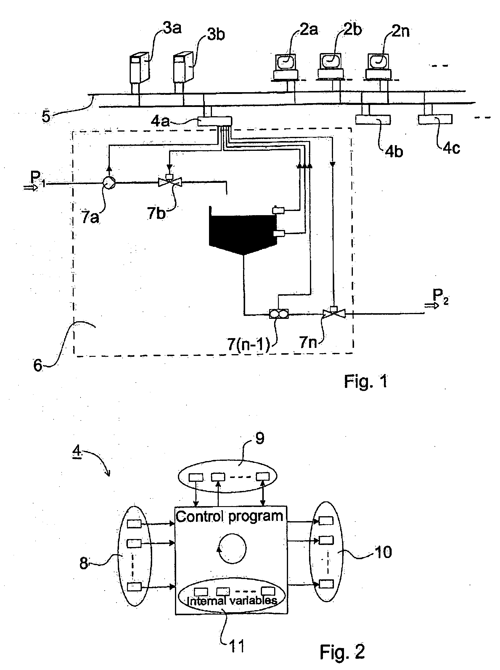
[0024]With reference to FIG. 1 the layout of a typical process control system is shown. Process control systems 1 typically consist of operator and engineering workstations 2a, 2b, . . . , 2n, a number of servers 3a, 3b for performing various kinds of system functionality and controllers 4a, 4b, . . . 4n performing the actual automatic process control functions. The different parts are interconnected by means of a communication network 5. The controllers 4a, 4b, . . . , 4n control a respective process section or function; in the figure the controller 4a is shown to control a process section 6 comprising a tank and a number of valves, actuators and sensors. Each process section or function, such as the process section 6, may be dependent upon an upstream and / or a downstream process section or function (not shown), as is indicated by the arrows P1 and P2.

[0025]A general principle for the execution of control programs in a controller is shown in FIG. 2. The controllers are typically pr...


PUM


Abstract

The invention relates to a method for evaluating an application for controlling a process within an automation system. The application is stored within a controller, and at least two versions of it are present within the controller. The method comprises the steps of: inputting to the different versions of the application an input signal obtained from the process; executing, in the controller, tasks based on this input signal for the different versions; generating a report comprising comparisons of the outputs from the different versions of the application; and evaluating, based on the generated report, the version(s) not used for controlling the process. An improved way of revising an automation system is thereby achieved. The invention also relates to such controller and an automation system.

Description

CROSS-REFERENCE TO RELATED APPLICATIONS[0001]The present application is a continuation of pending International patent application PCT / SE2007 / 000189 filed on Feb. 28, 2007 which designates the United States and claims priority from Swedish patent application 0600447-7 filed on Mar. 2, 2006, the content of which is incorporated herein by reference.FIELD OF THE INVENTION[0002]The invention relates to the field of automation, and in particular to a method for evaluating an application for controlling a process within an automation system as defined in the preamble of claim 1, to an automation system as defined in the preamble of claim 13, and to a controller as defined in the preamble of claim 19.BACKGROUND OF THE INVENTION[0003]Automatic control or automation is very important within industrial production, for example in order to eliminate monotonous tasks and lessen hazardous elements in a production line. In general automation also increases the efficiency as well as the quality of ...

Claims


Application Information

Patent Timeline
IPC IPC(8): G05B11/00G06F11/36
CPCG05B2219/31418G06F9/451G06F8/60G06F7/20
Inventor MEYER, MIKAELPAULY, THOMAS
Owner ABB (SCHWEIZ) AG
Why Eureka
Try Eureka