System for contactless moving or holding magnetic body in working space using magnet coil

a magnetic body and working space technology, applied in the field of contactless moving or holding magnetic bodies in working space using magnet coils, can solve the problems of not being able to achieve unrestricted navigational freedom of magnetic bodies, and allowing magnetic bodies to be held

Inactive Publication Date: 2005-05-05
SIEMENS AG
View PDF8 Cites 33 Cited by
  • Summary
  • Abstract
  • Description
  • Claims
  • Application Information

AI Technical Summary

Benefits of technology

[0024] The system according to the invention advantageously makes it possible to ensure interaction of position control for the magnetic body in the three spatial directions with the complex requirements for the field configuration, as is produced by the abovementioned magnet coil arrangement. Whenever the magnetic body is moved or rotated, the currents in this case change in all fourteen individual coils. The coil currents in the individual coils are in this case set such that the error between the set position and the actual position is reduced, in particular being minimized. The components used for setting and processing are designed appropriately.
[0025] Furthermore, the refinement with force feedback to the device for setting the orientation, set position and movement direction, as well as possible limiting of the speed at which the magnetic body is moved are advantageous. In particular, this allows free, stable floating (as is desirable for medical diagnosis) in a working space, for example of a video capsule which is equipped with a magnetic body in the form of a ferromagnet or permanent magnet, in accordance with the cited DE 101 42 253 C1, in a sample by active position control.
[0030] eight of the individual coils to form two coil arrangements that can be situated seen in the z direction one behind the other on the at least one tubular peripheral surface, and whose respectively four individual coils can be arranged distributed seen in a circumferential direction on the peripheral surface, and can serve to produce three nondiagonal elements, located on one side of the diagonal, in the gradient matrix. This coil system is distinguished by a clear design with good accessibility to the working space in the z direction.
[0036] In the embodiments described above, the field gradient coils situated on the (imaginary) peripheral surface can advantageously be fashioned in the form of a saddle. It is possible in this case for the end-face arcuate parts running on the peripheral surface in a circumferential direction to be situated next to one another as seen in this circumferential direction, that is to say to assume an angle of arc of >90° in each case, or else for them to overlap. It is easy to manufacture appropriate individual coils which produce clear field conditions.
[0037] Moreover, at least a few of the field component coils can be fashioned as flat rectangular coils or circular coils. In particular, the coils located at the end faces thus permit good access to the working space in the z direction.
[0039] In order to drive the fourteen individual coils of the magnet coils, it is advantageous to use a computer to drive its respectively assigned power supply as a function of the respective position of the magnetic body to be moved.

Problems solved by technology

However, the probes used in this case can be navigated only in limited fashion, particularly at branching points, and so contactless exertion of force from outside could be attended by an expansion of the field of application.
However, it is not possible to achieve unrestricted navigational freedom of the magnetic body with the aid of a magnet coil system composed of six individual coils.
None of the systems mentioned above allows a magnetic body to be held in a free-floating manner at a predetermined point with the aid of magnetic fields.

Method used


Image

  • System for contactless moving or holding magnetic body in working space using magnet coil
  • System for contactless moving or holding magnetic body in working space using magnet coil
  • System for contactless moving or holding magnetic body in working space using magnet coil

Examples


Embodiment Construction

[0047] Reference will now be made in detail to the preferred embodiments of the present invention, examples of which are illustrated in the accompanying drawings, wherein like reference numerals refer to like elements throughout.

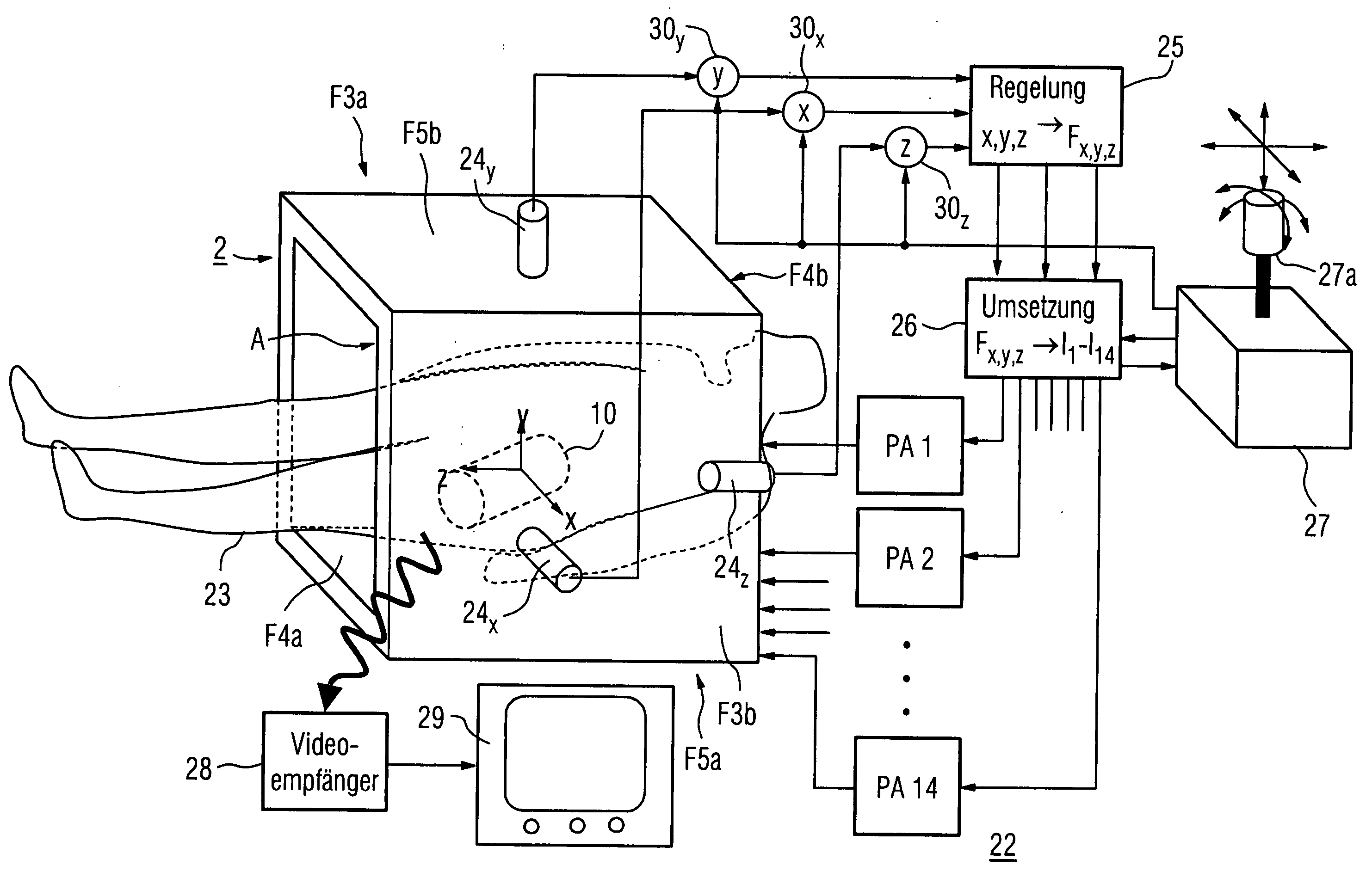
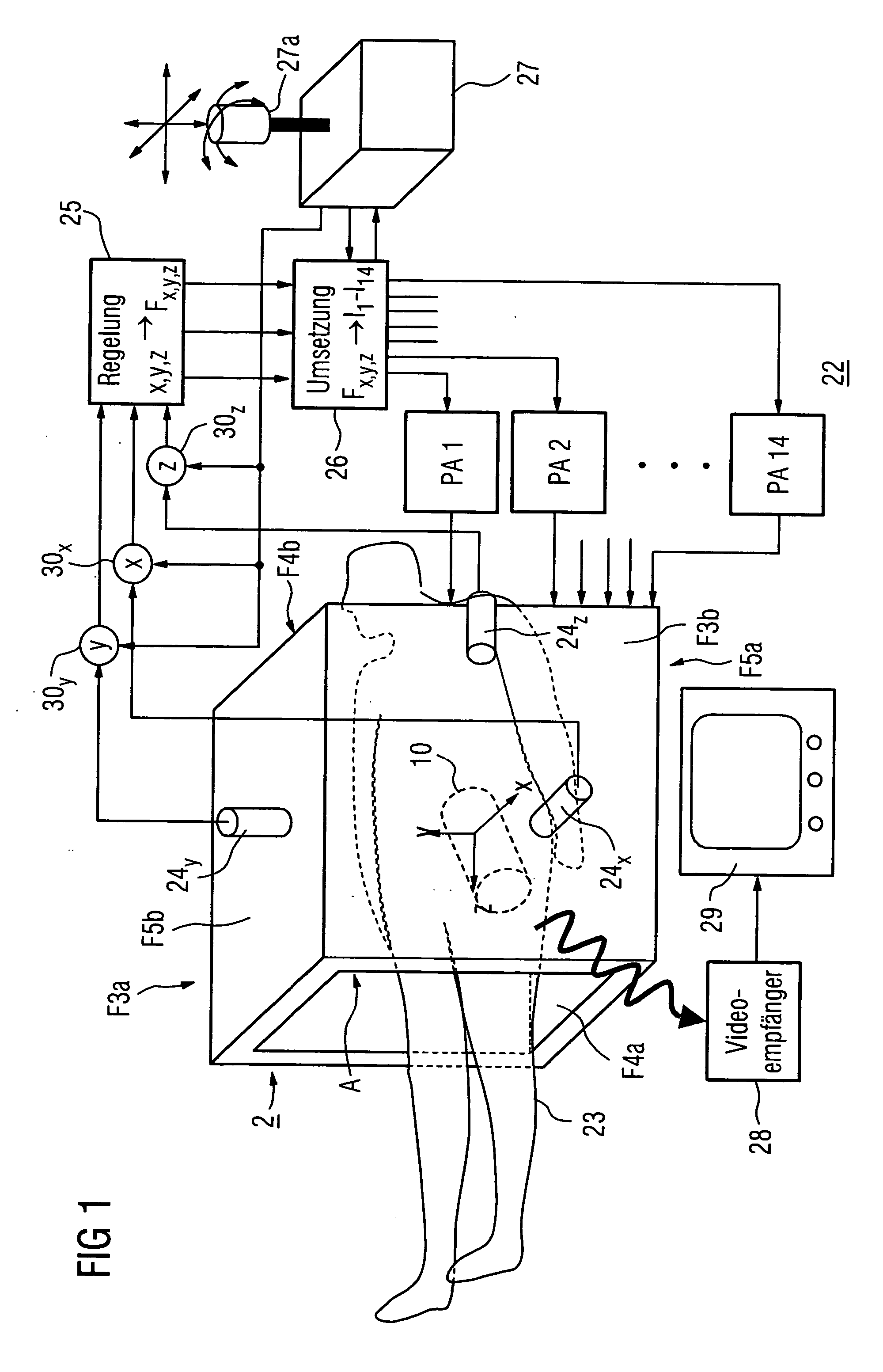
[0048] A system according to the invention can be used to move a magnetic test specimen in a contactless fashion in a working volume and to hold it steady. In this case, the alignment as well as the magnitude and direction of the forces on this test specimen can be prescribed from outside magnetically and without mechanical connection. Particularly in medical applications, it is possible thereby for a probe fitted with such a magnetic test specimen to be a catheter or an endoscope having magnet elements or a small television camera with an illumination system and transmitter that transmits video images from the interior of the body such as, for example, the digestive tract or the lung. Moreover, ferromagnetic foreign bodies such as, for example, a needle or...


PUM


Abstract

A magnetic body may be moved in a contactless fashion and fixed in a working space by a system with a magnet coil system of fourteen individual coils which can be driven individually for production of three magnetic field components and five magnetic field gradients. The system also includes a unit to detect the actual position and a unit to set a desired position of the magnetic body.

Description

CROSS REFERENCE TO RELATED APPLICATIONS [0001] This application is based on and hereby claims priority to German Application No. 103 41 092.9 filed on 5 Sep. 2003, the contents of which are hereby incorporated by reference. BACKGROUND OF THE INVENTION [0002] 1. Field of the Invention [0003] An aspect of the invention relates to a system for at least one of contactless moving and fixing, i.e., holding in position, a magnetic body in a three-dimensional working space that is surrounded by surfaces defined in a rectangular x,y,z coordinate system, using a magnet coil system which surrounds the working space. [0004] 2. Description of the Related Art [0005] Use is made in medicine of endoscopes and catheters that are introduced via incisions or body orifices, and can be displaced in a longitudinal direction from outside and can thus be navigated only in one dimension. Light guides permit optical inspection, it being possible to use control wires to rotate an endoscope pipe and thus the v...

Claims


Application Information

Patent Timeline
Patent Type & Authority Applications(United States)
IPC IPC(8): A61B1/00A61B5/06A61B5/07A61B19/00
CPCA61B1/00147A61B1/00158A61B5/06A61B2019/2261A61B19/22A61B2019/2253A61B5/062A61B34/73A61B2034/732A61B34/70
Inventor RIES, GUNTER
Owner SIEMENS AG
Why Eureka
Try Eureka