Self temperature-compensated high precision event timer using standard time reference frequency and its method

a high-precision, event-timer technology, applied in the field of high-precision event-timers, can solve the problems of small size and different inherent characteristics of high-precision event-timers, and achieve the effect of reducing the error between related instruments and minimizing the temperature

Active Publication Date: 2013-01-10
KOREA ASTRONOMY & SPACE SCI INST
View PDF7 Cites 6 Cited by
  • Summary
  • Abstract
  • Description
  • Claims
  • Application Information

AI Technical Summary

Benefits of technology

[0022]It is an object of the present invention to provide a self temperature-compensated high precision event timer using a standard time reference frequency and its method which make it possible to measure a precision event time in such a way to make a reference data in accordance with a standard time reference frequency signal and to make a measurement data by using an apparatus with the same structure as a reference data with respect to a signal to be measured and to compare the measurement data with a reference data, whereby temperature effects can be minimized by making the time changes, which would occur due to the temperature changes occurring between two apparatuses, happen equally, by providing the same structure and parts to a reference signal circuit apparatus for an event time measurement and a signal circuit apparatus. In addition, the zero point adjustment can be performed during a real time operation, and it does not need stop the apparatus during the zero point adjustment. A small size instrument can be manufactured in such a way that a delay circuit is made by a small size semiconductor, and an error between related instruments can be significantly reduced.

Problems solved by technology

Since the waves are formed by the CFD 2 using a delay line the volume of which is larger than electronic elements, there are a lot of problems in manufacturing a small size high precision event timer.
The characteristics of delay lines are different depending on parts since the delay lines are made manually, which results in different inherent characteristics at each time signal detector which is made from the above problematic parts.

Method used


Image

  • Self temperature-compensated high precision event timer using standard time reference frequency and its method
  • Self temperature-compensated high precision event timer using standard time reference frequency and its method
  • Self temperature-compensated high precision event timer using standard time reference frequency and its method

Examples


Embodiment Construction

[0036]The preferred embodiments of the present invention will be described with reference to the accompanying drawings.

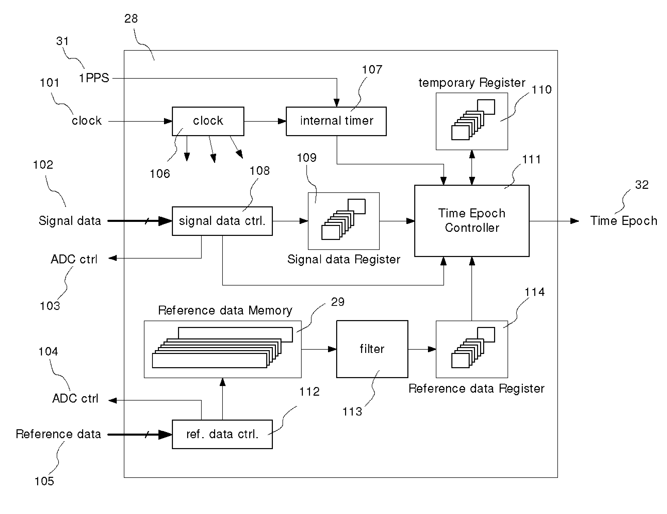
[0037]FIG. 3 is a view of a construction of a high precision event timer according to an embodiment of the present invention.

[0038]The present invention is substantially characterized in that the analog signal process procedures of a measurement signal and a reference signal are constructed in the same manner.

[0039]FIG. 3 shows a detailed analog process procedure. In the analog process procedure, the process of each signal might have different results like the conventional art depending on the electrical characteristics of electrical elements. In the present invention, the signals are processed with the same element and under the same conditions for minimizing the differences which might occur due to the changes in temperatures.

[0040]The above construction will be described in details.

[0041]As show in FIG. 3, the high precision event timer according to an embodiment...


PUM


Abstract

The present invention makes it possible to measure a precision event time in such a way to make a reference data in accordance with a standard time reference frequency signal and to make a measurement data by using an apparatus with the same structure as a reference data with respect to a signal to be measured and to compare the measurement data with a reference data, whereby temperature effects can be minimized by making the time changes due to temperature changes occurring between two apparatuses happen equally, by providing the same structure and parts to a reference signal circuit apparatus for an event time measurement and a signal circuit apparatus to be measured, and the zero point adjustment is performed during the real time operation, so the system is not needed to stop.

Description

TECHNICAL FIELD[0001]The present invention relates to a high precision event timer, and in particular to a self temperature-compensated high precision event timer using a standard time reference frequency and its method which make it possible to measure a precision event time in such a way to make a reference data in accordance with a standard time reference frequency signal and to make a measurement data by using an apparatus with the same structure as a reference data with respect to a signal to be measured and to compare the measurement data with a reference data, whereby temperature effects can be minimized by making the time changes, which would occur due to temperature changes occurring between two apparatuses, happen equally, by providing the same structure and parts to a reference signal circuit apparatus for an event time measurement and a signal circuit apparatus.BACKGROUND ART[0002]A distance measurement method using a pulse laser is, generally, directed to computing a fl...

Claims


Application Information

Patent Timeline
Patent Type & Authority Applications(United States)
IPC IPC(8): G04F10/00
CPCG04F10/005G04F10/00G04F10/04G04G3/04G01B11/14G01S7/523G04F13/02
Inventor BANG, SEUNG CHEOLLIM, HYUNG CHULPARK, JONG UK
Owner KOREA ASTRONOMY & SPACE SCI INST
Why Eureka
Try Eureka