Speaker arrangement for communication terminal

a technology for communication terminals and speakers, applied in the field of communication terminals, can solve the problems of speaker beside the resonance chamber, less good acoustics, and almost impossible to seal a phone, and achieve the effects of reducing the outer terminal dimensions, eliminating the thickness contribution of the speaker, and good resonance chamber

Inactive Publication Date: 2007-06-19
SONY ERICSSON MOBILE COMM AB
View PDF16 Cites 46 Cited by
  • Summary
  • Abstract
  • Description
  • Claims
  • Application Information

AI Technical Summary

Benefits of technology

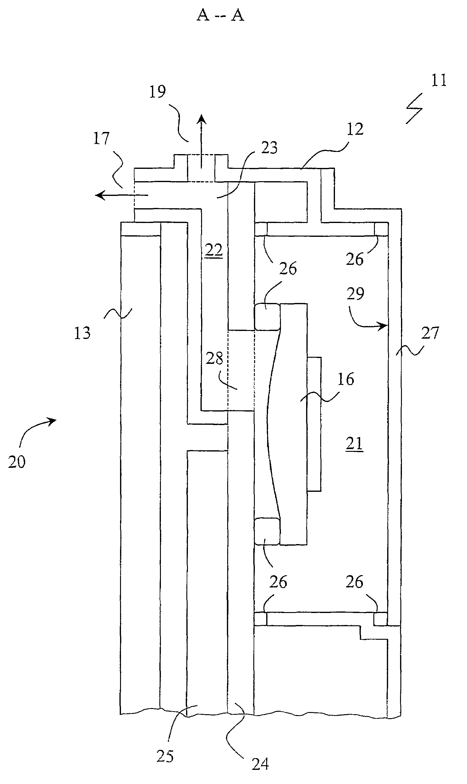
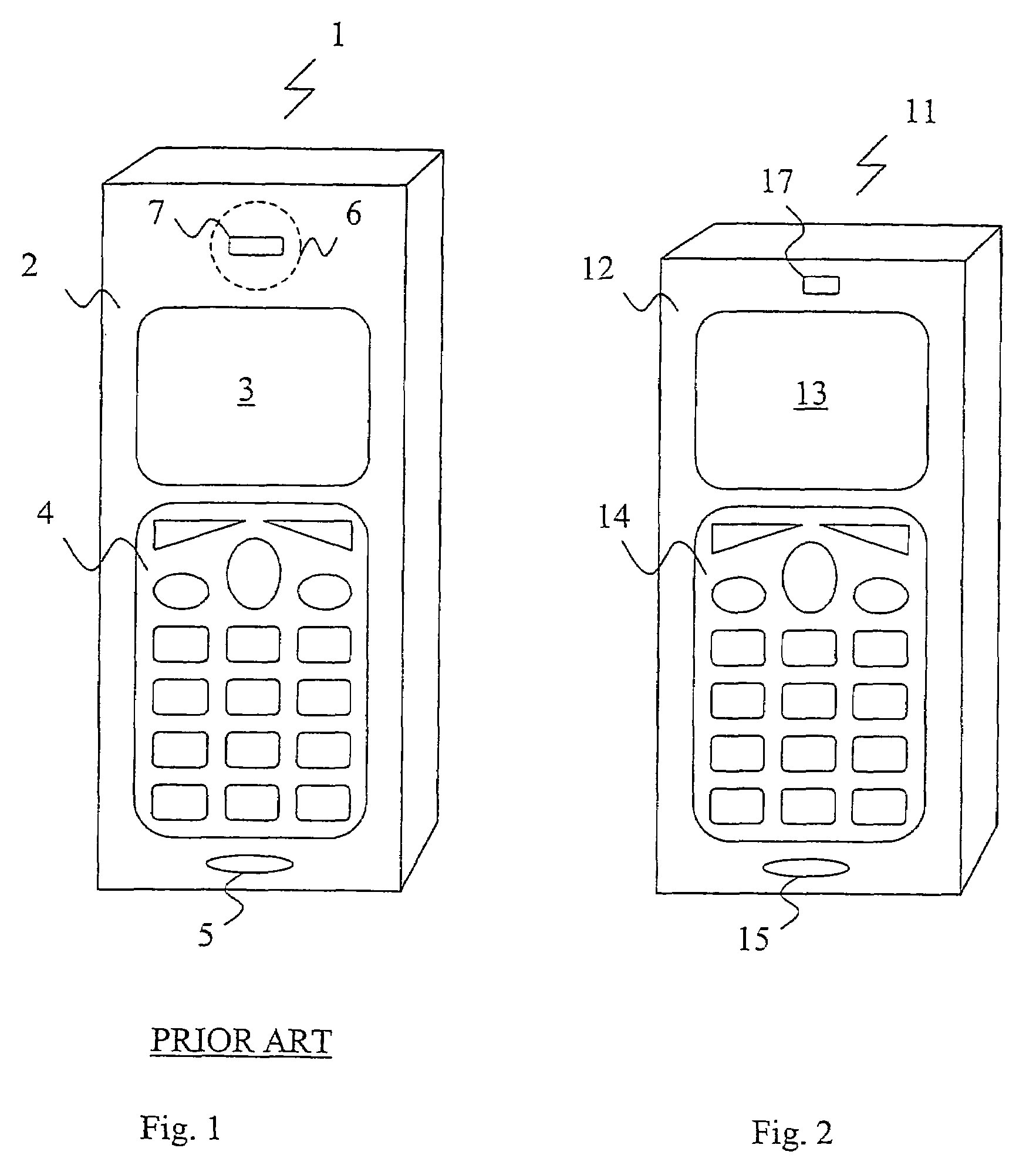
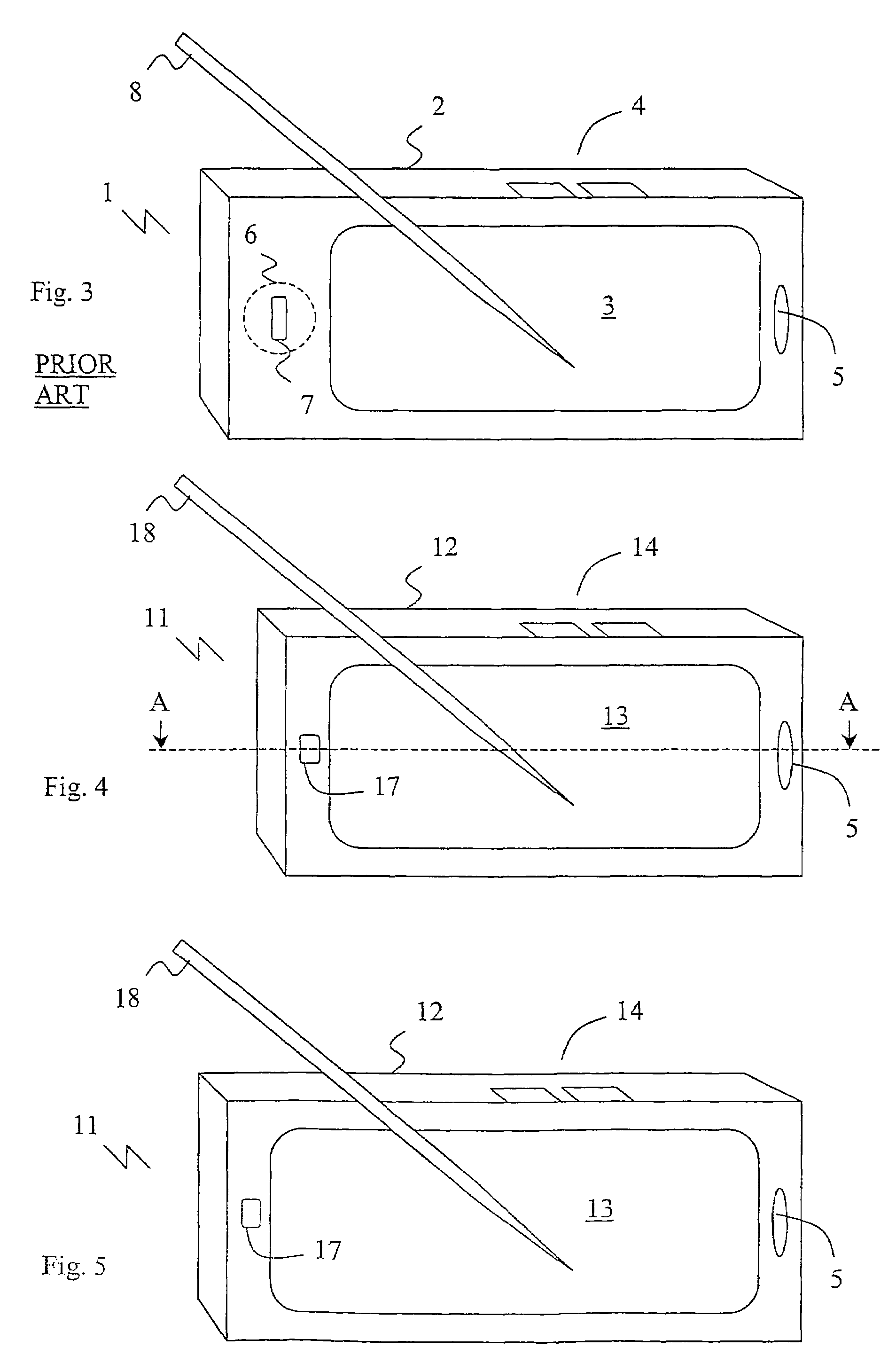
[0010]It is consequently an object of the present invention to overcome the deficiencies related to the state of the art communication terminal as recited above. More specifically, it is an object to provide a speaker arrangement for a communication terminal making it possible to decrease the outer terminal dimensions. According to the present invention, this object is fulfilled by communication terminal comprising a housing carrying therein a radio antenna element, a speaker, and a chamber acting as an electromagnetic resonance cavity for the antenna as well as an acoustic resonance cavity for the speaker. According to the invention, the speaker is mounted inside said chamber and is coupled to the outside of the housing through a sound outlet. By using the antenna cavity a good resonance chamber is provided for the speaker. Furthermore, by placing the speaker inside the cavity, the thickness contribution of the speaker is eliminated. Tests performed on a prototype apparatus have shown the surprising result that the speaker will not, or to a very little extent, affect the performance of the antenna.
[0013]In one embodiment, the speaker and the user interface are placed next to each other. However, a first part of the ground plane is located adjacent to the front part of the housing over the speaker antenna, and a second part of the ground plane is located under the user interface, wherein said first and second parts are connected by a bent portion of the ground plane. This way the top portion of the terminal, comprising the antenna and the speaker, will basically be confined between the ground plane, i.e. the first part thereof, and the antenna element, rendering a very slim profile. The bent portion allows for the two parts of the ground plane to be arranged at different levels, though potentially parallel to each other. This way the user interface, which has a certain thickness, can be positioned with its front face basically in the same plane as the front side of the top portion.

Problems solved by technology

In a normal case the whole phone is used as a back volume, but it is almost impossible to seal a phone.
Since the speaker performances is highly dependent on the dimension, reduction of the speaker size results in less good acoustics.
However, the arrangement of the speaker beside the resonance chamber has some drawbacks.

Method used


Image

  • Speaker arrangement for communication terminal
  • Speaker arrangement for communication terminal
  • Speaker arrangement for communication terminal

Examples


Embodiment Construction

[0024]The present description refers to communication terminals as a device in which to implement the speaker configuration according to the present invention. The communication terminal includes all mobile equipment devised for radio communication with a radio station, which radio station may also be a mobile terminal or e.g. a stationary base station. Consequently, the term “communication terminal” includes mobile phones, pagers, communicators, electronic organizers, smart phones, PDA:s (Personal Digital Assistants), vehicle-mounted radio communication devices or the like, as well as portable laptop computers devised for wireless communication in for instance WLAN (Wireless Local Area Network). Furthermore, since the design and present invention is suitable for but not restricted to mobile use, the term “communication terminal” should also be understood as to include any stationary device arranged for radio communication, such as for instance desk top computers, printers, fax mach...


PUM


Abstract

A communication terminal includes a housing carrying therein a radio antenna element, a speaker, and a chamber that acts as an electromagnetic resonance cavity for the antenna and as an acoustic resonance cavity for the speaker. The speaker is mounted inside the chamber and is coupled to the outside of the housing through a sound channel. The terminal includes a user interface on a front side of the housing and the speaker is placed behind the user interface as viewed from the front side, with the sound channel extending from a channel inlet at the speaker to a channel front outlet at the front side.

Description

RELATED APPLICATIONS[0001]The present application is a 35 U.S.C. §371 national phase application of PCT International Application No. PCT / EP2003 / 006724, having an international filing date of Jun. 26, 2003, and claiming priority to European Patent Application No. 02077565.6, filed Jul. 1, 2002, and U.S. Provisional Application No. 60 / 394,404, filed Jul. 8, 2000 the disclosures of which are incorporated herein by reference in their entireties. The above PCT International Application was published in the English language and has International Publication No. WO 2004 / 004408 A1.FIELD OF THE INVENTION[0002]The present invention relates generally to a communication terminal comprising an antenna for wireless communication purposes, and a speaker for conveying audio information to a user of the communication terminal. More specifically the invention relates to a communication terminal wherein such a speaker is arranged inside the resonance chamber of said antenna.BACKGROUND[0003]The mobile...

Claims


Application Information

Patent Timeline
Patent Type & Authority Patents(United States)
IPC IPC(8): H04R1/02G10K11/22H01Q1/24H04M1/00H04M1/02H04M1/03H04R1/00H04R1/28
CPCH04M1/035H01Q1/243H04R1/025H04R2499/11H04B1/38H04M1/02H04M1/03H04R1/02
Inventor ERIXON, MATSSCHACK, GORANFROHLUND, STIGSIMONSSON, OLOF
Owner SONY ERICSSON MOBILE COMM AB
Why Eureka
Try Eureka