Device for insertion of implants

a technology for implants and insertion devices, applied in the field of implants insertion devices, can solve the problems of difficult insertion of implants, wall implants, and inability to work well, and achieve the effect of improving the rotational control of implants and minimizing the size of incisions in patients

Active Publication Date: 2007-06-26
DEPUY SPINE INC (US)
View PDF28 Cites 222 Cited by
  • Summary
  • Abstract
  • Description
  • Claims
  • Application Information

AI Technical Summary

Benefits of technology

[0014]The invention has many advantages. For example, embodiments of the invention provide for insertion of implants, which can be thin walled, into a patient while minimizing the size of the incision in the patient. Additionally, improved rotational control of the implant during implantation is achieved.

Problems solved by technology

Unfortunately, insertion of implants can be challenging.
However, this approach does not work well with thinner wall implants that may not have enough material to support threads or there are too few threads to prevent stripping.
This can also be problematic for different materials, such as polyetheretherketone (PEEK) or carbon fiber reinforced polymers (CFRP).
These particular materials have the advantage of radiolucency, but tend to be brittle or lack necessary strength to support threads.

Method used


Image

  • Device for insertion of implants
  • Device for insertion of implants
  • Device for insertion of implants

Examples


Embodiment Construction

[0028]The foregoing and other objects, features and advantages of the invention will be apparent from the following more particular description of various embodiments of the invention, as illustrated in the accompanying drawings in which like reference characters refer to the same parts throughout the different views. The drawings are not necessarily to scale, emphasis instead being placed upon illustrating the principles of the invention.

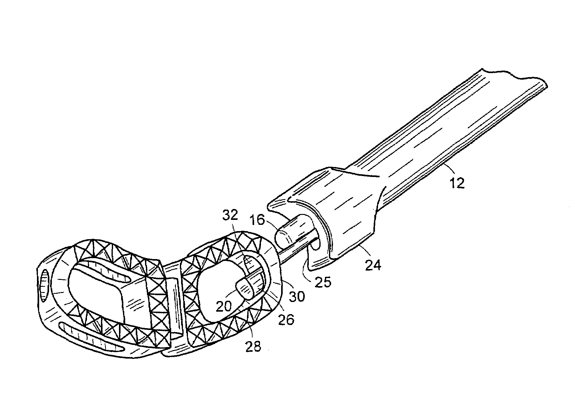
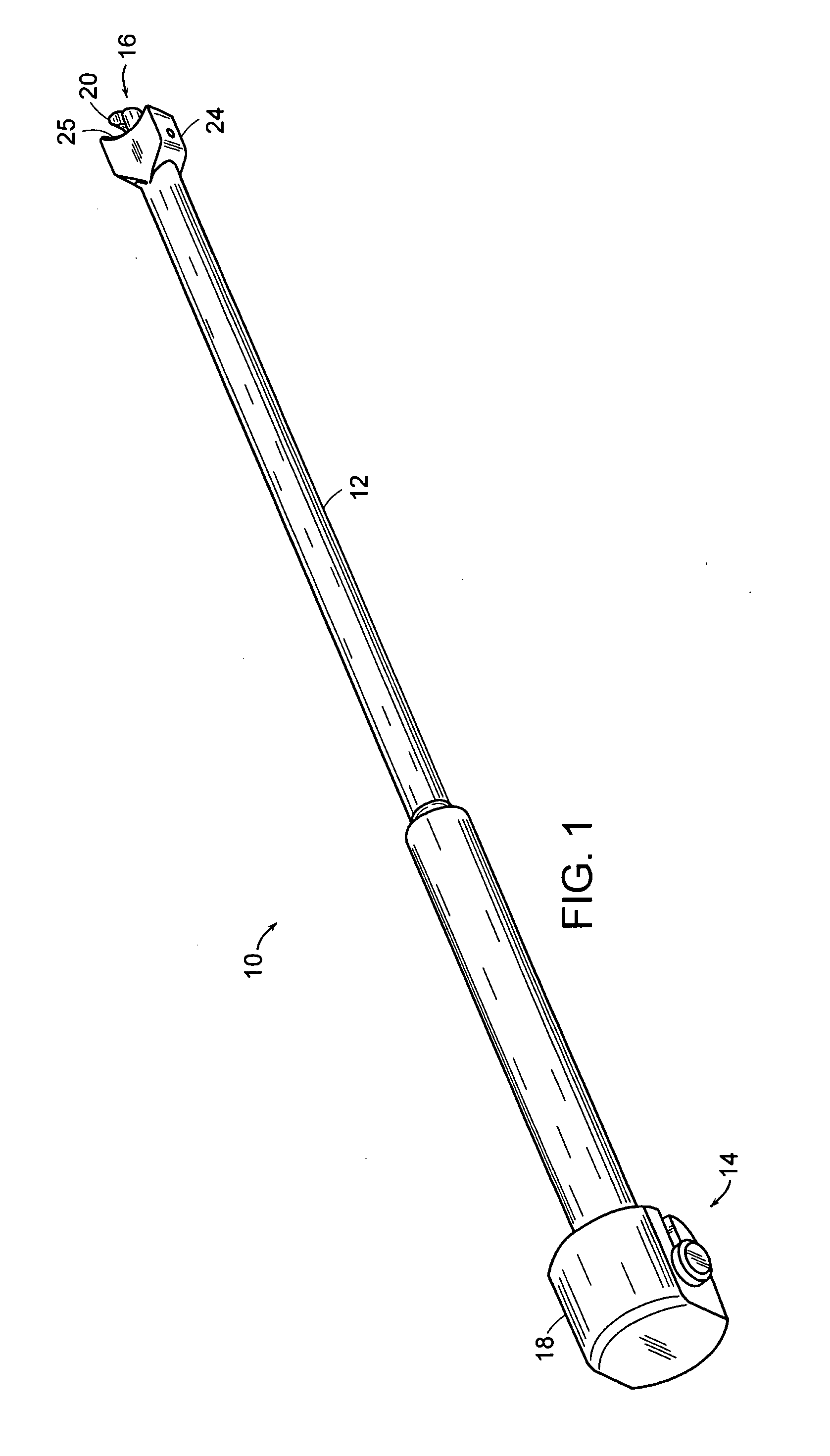
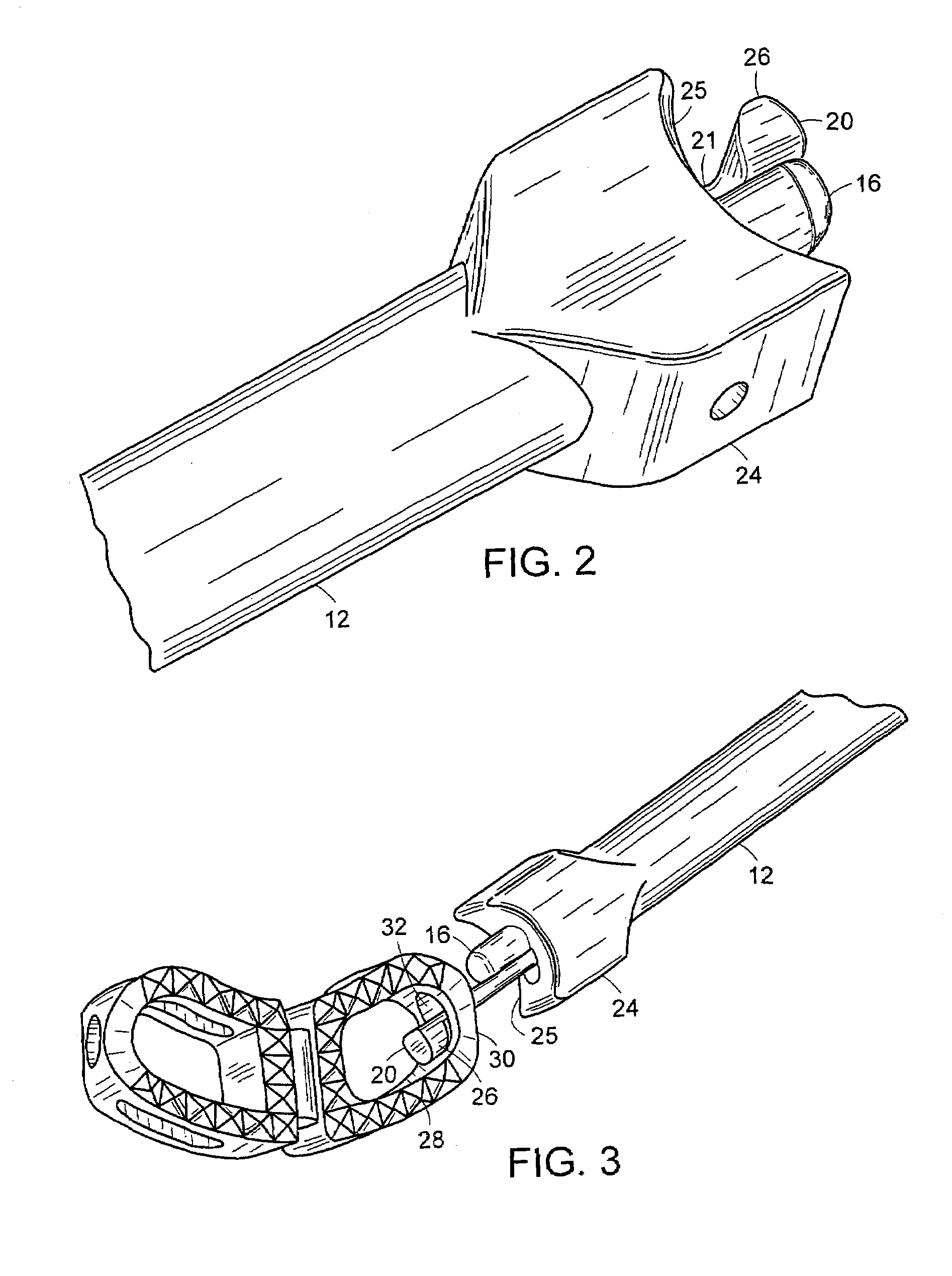
[0029]FIG. 1 illustrates an embodiment of a device 10 for insertion of implants. In this embodiment, the device 10 includes a shaft 12 having a proximal end 14 and a distal end 16. A knob 18, positioned on the proximal end 14 of the shaft 12, is rotatable to cause a moveable element 20 to move within a conduit provided within the shaft 12. In particular embodiments, the conduit can be open on at least one side, for example, the shaft 12 can be U-shaped, C-shaped, or dovetail-shaped in cross section. In alternative embodiments, the moveable element ...


PUM


Abstract

A device and method, which can be used for insertion of surgical implants, are provided in which the device includes a shaft having a proximal end and a distal end, and at least one moveable element. In a particular embodiment, the moveable element is disposed within a conduit defined by the shaft. The moveable element includes a leg extending through the conduit and a foot at an end of the leg proximal to the distal end of the shaft. The element is moveable relative to the shaft between a first position, wherein the foot extends beyond the distal end, and a second position, wherein the foot is substantially adjacent to the distal end. The device can further include a surgical implant that can be removably attached to the distal end.

Description

BACKGROUND OF THE INVENTION[0001]Implants can be used, for example, to fuse spinal vertebrae to alleviate pain and discomfort associated with injured intervertebral disks. Unfortunately, insertion of implants can be challenging. Often the device for insertion of implants, which can be referred to as an inserter, is required to mechanically attach to the implant and provide rotational control. This provides the surgeon with the ability to control the implant and achieve the desired positioning within the patient during insertion of the implant. Once the implant is positioned within the patient, the inserter is disengaged from the implant.[0002]One prior art system utilizes a threaded insertion mechanism that pulls the implant into an anti-rotation feature. However, this approach does not work well with thinner wall implants that may not have enough material to support threads or there are too few threads to prevent stripping. This can also be problematic for different materials, such...

Claims


Application Information

Patent Timeline
Patent Type & Authority Patents(United States)
IPC IPC(8): A61B17/88A61F2/00A61F2/30A61F2/44A61F2/46
CPCA61F2/4465A61F2/4611A61F2002/30133A61F2002/30777A61F2002/30787A61F2002/30843A61F2002/4627A61F2002/4628A61F2230/0015
Inventor BARTISH, CHARLESBROUSSEAU, JEFFKONIECZYNSKI, DAVIDCONNOLLY, STEPHEN
Owner DEPUY SPINE INC (US)
Why Eureka
Try Eureka