Surgical cannula with bellows

a cannula and bellow technology, applied in the field of surgical cannulas, can solve the problems of post-procedure discomfort for patients and less than ideal, and achieve the effect of reducing the size of the incision

Inactive Publication Date: 2019-09-12
MIKOL EDWARD J
View PDF0 Cites 0 Cited by
  • Summary
  • Abstract
  • Description
  • Claims
  • Application Information

AI Technical Summary

Benefits of technology

[0029]In another embodiment, the inventive cannula comprises a lumen with multiple flow channels defined within the wall of the lumen or defined thereon. The lumen is attached at the proximal end to a manifold, a bellows and a rotating cap. The manifold comprises layers that are rotatable relative to each other. One layer defines various ports that are connected to the flow channels defined in or on the lumen wall. Another layer is rotatable to select which port(s) to open or close to effect flow into the inner lumen membrane, the outer anchor / seal membrane and the bellows. The cap is rotated toward the manifold to squeeze the fluid from the bellows into one or both membranes to pressurize same.
[0030]In another embodiment, the cannulas of the present invention can be manufactured by 3-D printing in whole or in part, preferably, the portion(s) of the cannulas that contain flow channels. An advantage of 3-D printing is that the sidewall of the lumen of the cannula can be printed to be thin with flow channels to minimize the incision size.

Problems solved by technology

This is less than ideal because there is no positive pressure gradient from the inflated internal membrane to the body cavity for a positive seal.
These anchoring protrusions are rigid and are pressed against the incision site, which may cause post-procedure discomfort for the patient.

Method used


Image

  • Surgical cannula with bellows
  • Surgical cannula with bellows
  • Surgical cannula with bellows

Examples


Embodiment Construction

Parts List

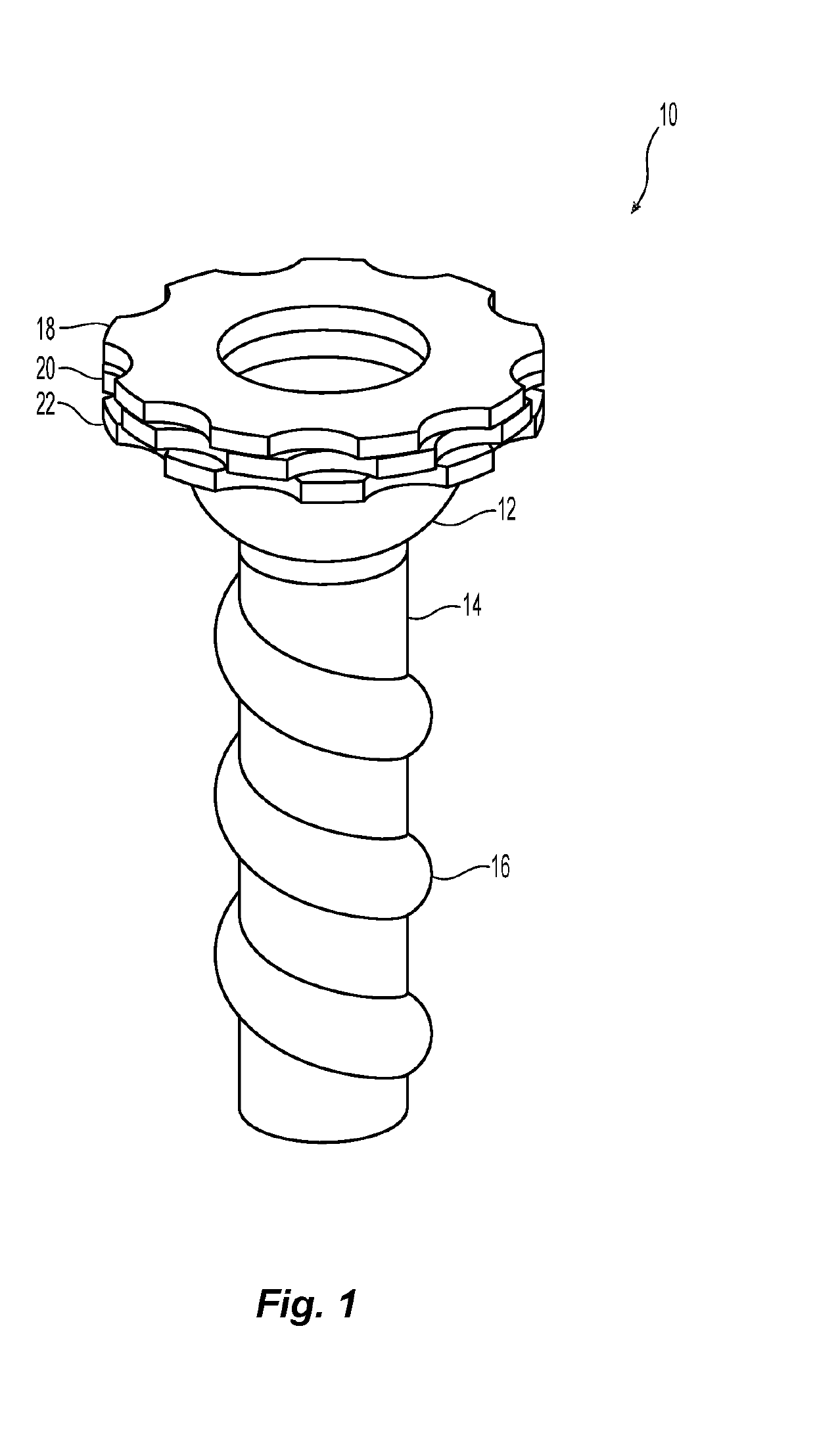
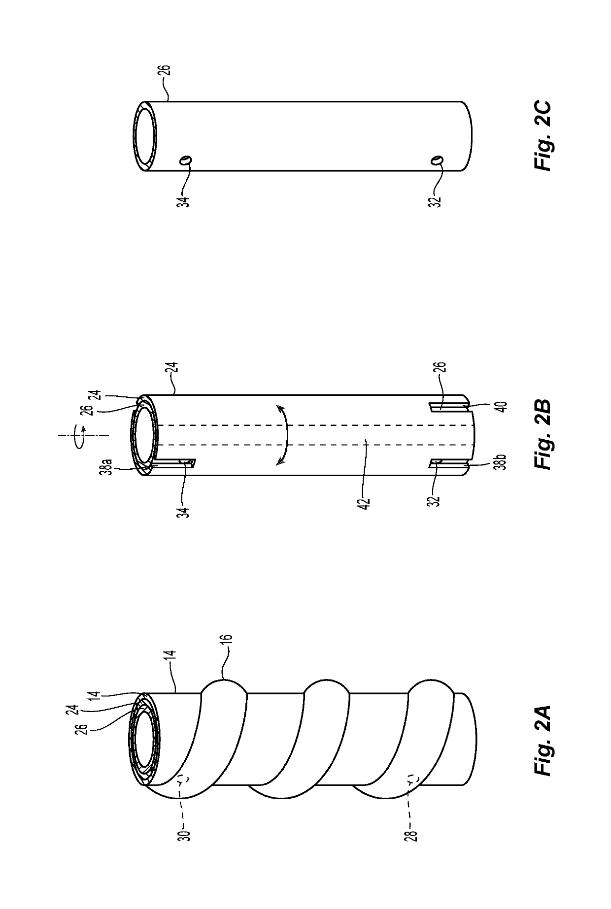
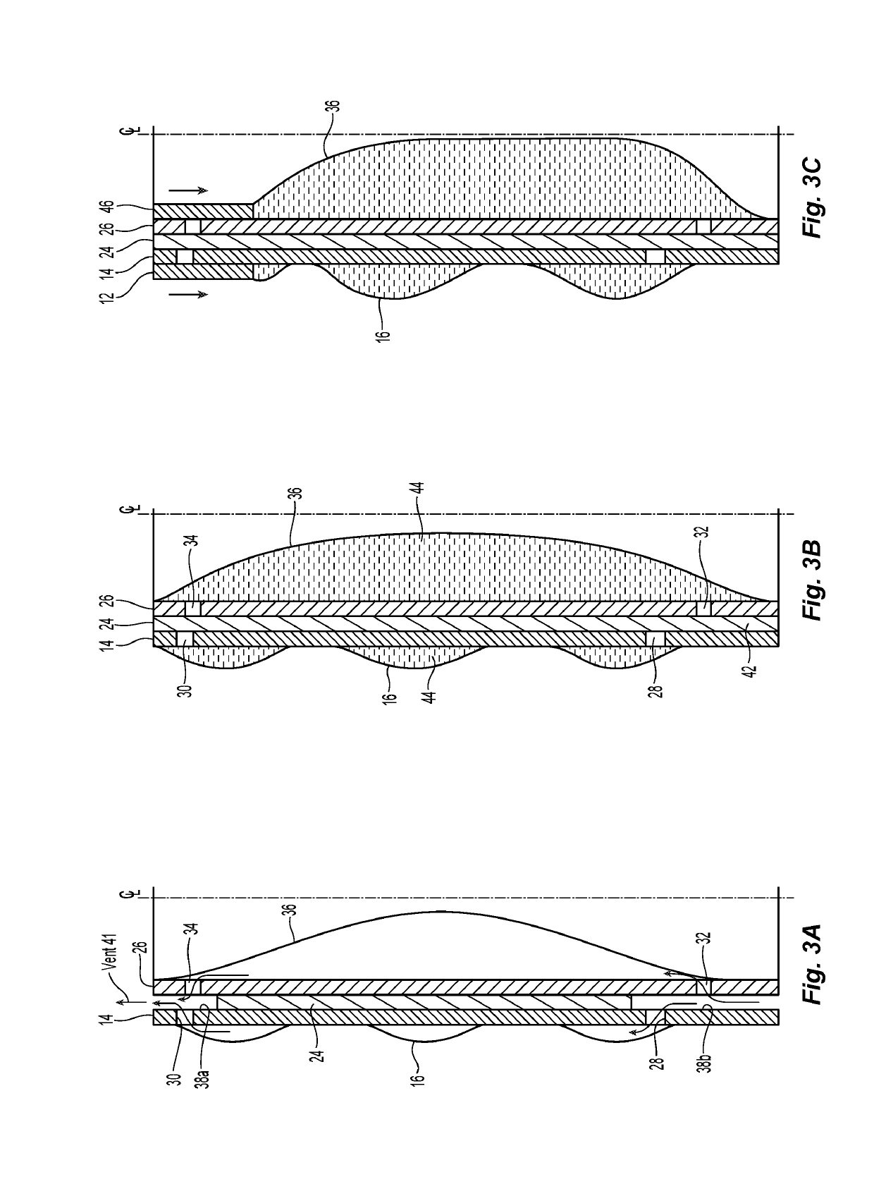
[0075]10 Inventive cannula[0076]12 Outer compression sleeve[0077]14 Anchor sleeve[0078]16 Anchor channel[0079]18 Control dial[0080]20 Control dial[0081]22 Control dial[0082]24 Flow sleeve[0083]26 Lumen wall, lumen body or external casing[0084]28 Ingress[0085]30 Egress[0086]32 Ingress[0087]34 Egress[0088]36 Lumen membrane[0089]38a, b Inflating flow channel[0090]39, 39a, 39b Duckbill valve[0091]40 Deflating flow channel[0092]41 Vent[0093]42 Seal area[0094]44 Insufflation fluid[0095]46 Inner compression sleeve[0096]48 Inflating flow channel[0097]50 Connecting flow channel[0098]52 Inflating flow channel[0099]100 Cannula[0100]102 Lumen wall, lumen body or external casing[0101]104 Inner lumen membrane[0102]106 Outer anchor / seal membrane[0103]108 Manifold[0104]110 Rotating cap[0105]112 Threaded connector[0106]114 Bellows[0107]115 External valve or seal, such as sealing stopper[0108]116 Covering or port layer[0109]118 Ports A-I[0110]120 Tabs O, I, B[0111]122 Rotating layer[0112]12...


PUM


Abstract

Disclosed herein are multiple cannulas defining a lumen sized and dimensioned to receive one or more medical instruments, an inflatable outer membrane attached to an outer surface of the cannula, and at least one activator that reversibly activates the cannulas to push a fluid contained in the cannulas into the outer membrane to fill or pressurize the outer membrane. Also disclosed are methods for operating these cannulas.

Description

FIELD OF THE INVENTION[0001]The present invention is directed to a surgical cannula with an improved ability to anchor and / or seal to the incision site and to the surgical instrument(s) inserted therethrough. The inventive surgical cannula can individually control various flow / vent paths to allow discrete controls of the outer anchor / seal membrane and the inner sealing membrane.BACKGROUND OF THE INVENTION[0002]Cannulas have been used in minimally invasive surgical procedures, such as laparoscopic and arthroscopic surgeries. Typically, in these procedures a small incision in made in the skin of a patient to access internal cavities, such as the abdomen or joints. A cannula is inserted into and is secured to the incision site. Surgical instruments are passed through the proximal openings of cannulas to enter a body cavity. During these procedures, the body cavity is inflated with an insufflated gas or liquid to create a surgical zone in the body cavity for surgical instruments. These ...

Claims


Application Information

Patent Timeline
Patent Type & Authority Applications(United States)
IPC IPC(8): A61B17/34A61B17/02A61M13/00
CPCA61B17/0218A61B2017/0225A61B17/3498A61B17/3439A61B2017/00557A61B17/3421A61B2017/3419A61M13/003A61B17/3423A61B2017/3486A61B2017/349
Inventor MIKOL, EDWARD J.THAN, HUNG T.
Owner MIKOL EDWARD J
Why Eureka
Try Eureka