Vessel hull transducer modular mounting system

Inactive Publication Date: 2007-06-26
SWCE
View PDF12 Cites 33 Cited by
  • Summary
  • Abstract
  • Description
  • Claims
  • Application Information

AI Technical Summary

Benefits of technology

[0009]The present invention is a vessel hull transducer modular mounting system which enables transducers to be replaced and

Problems solved by technology

This system has the disadvantage that the transducer is subject to noise from the vessel's engine and the turbulent movement of the water around the transducer and against the hull.
Undesirable noise interference compromises the ability of the transducer to provide a clear and highly useable signal.
Such mounting is also highly vulnerable to damage from floating objects, impact when docking, concussion from underwater detonation (such as mines) as well as stresses induced by the motion of waves.
They have been typically l

Method used


Image

  • Vessel hull transducer modular mounting system
  • Vessel hull transducer modular mounting system
  • Vessel hull transducer modular mounting system

Examples


Embodiment Construction

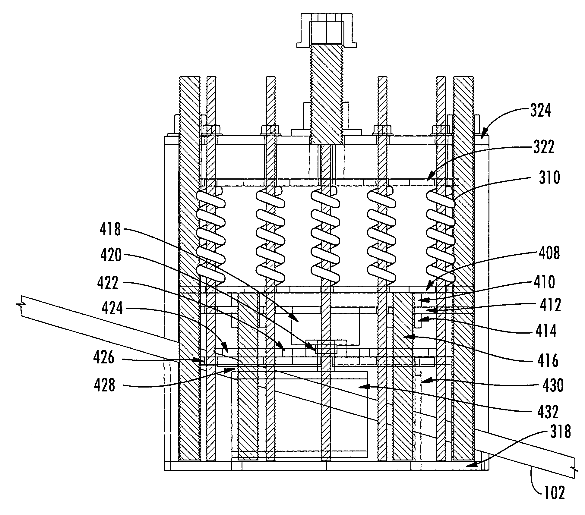
[0022]The present invention is a vessel hull transducer modular mounting system which enables transducers to be replaced and upgraded without necessitating the further modification of the hull and thus not necessitating the dry-docking of the vessel. A further feature of the present invention includes the ability to reduce and dampen acoustic shock impact on the transducer. Another feature of the present invention includes the ability to extend and retract the transducer.

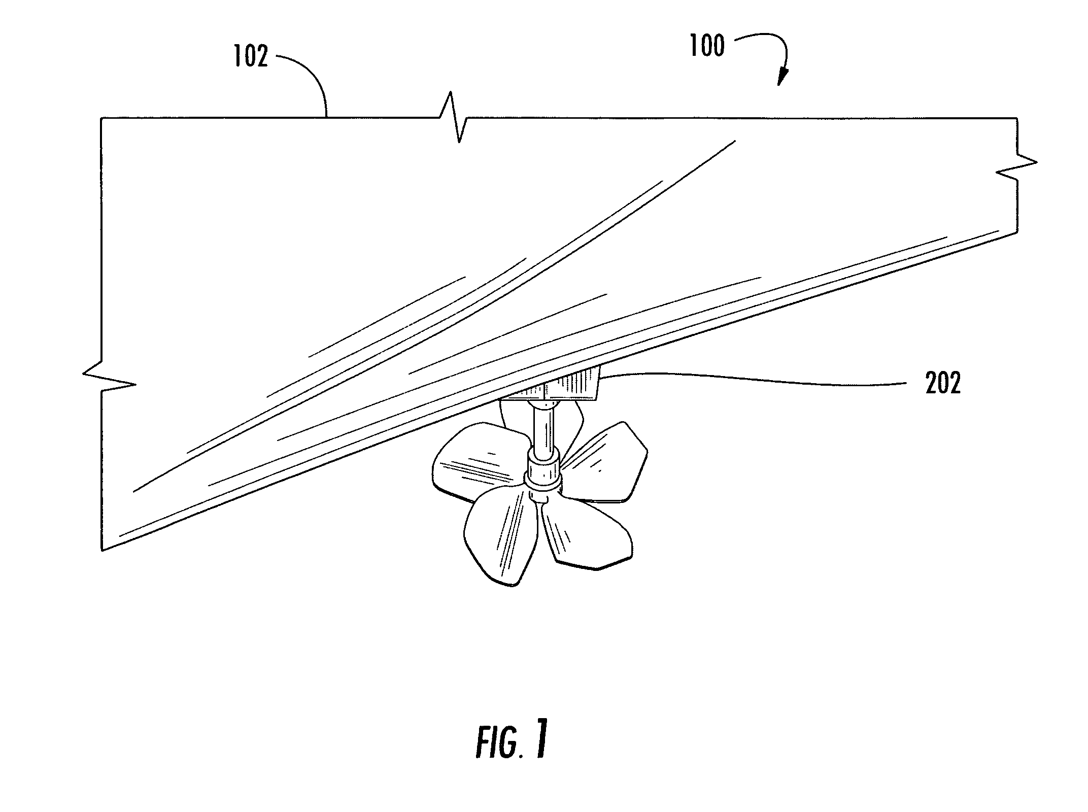
[0023]Referring to FIG. 1 there is shown a view of a portion of the vessel hull showing the transducer modular mounting system looking from the bow towards the stern under the vessel. Looking from the bow towards the stern from under the vessel 100 the exterior fairing 202 of the present invention transducer modular mounting system can be seen integrated into the vessel hull 102 of the vessel 100.

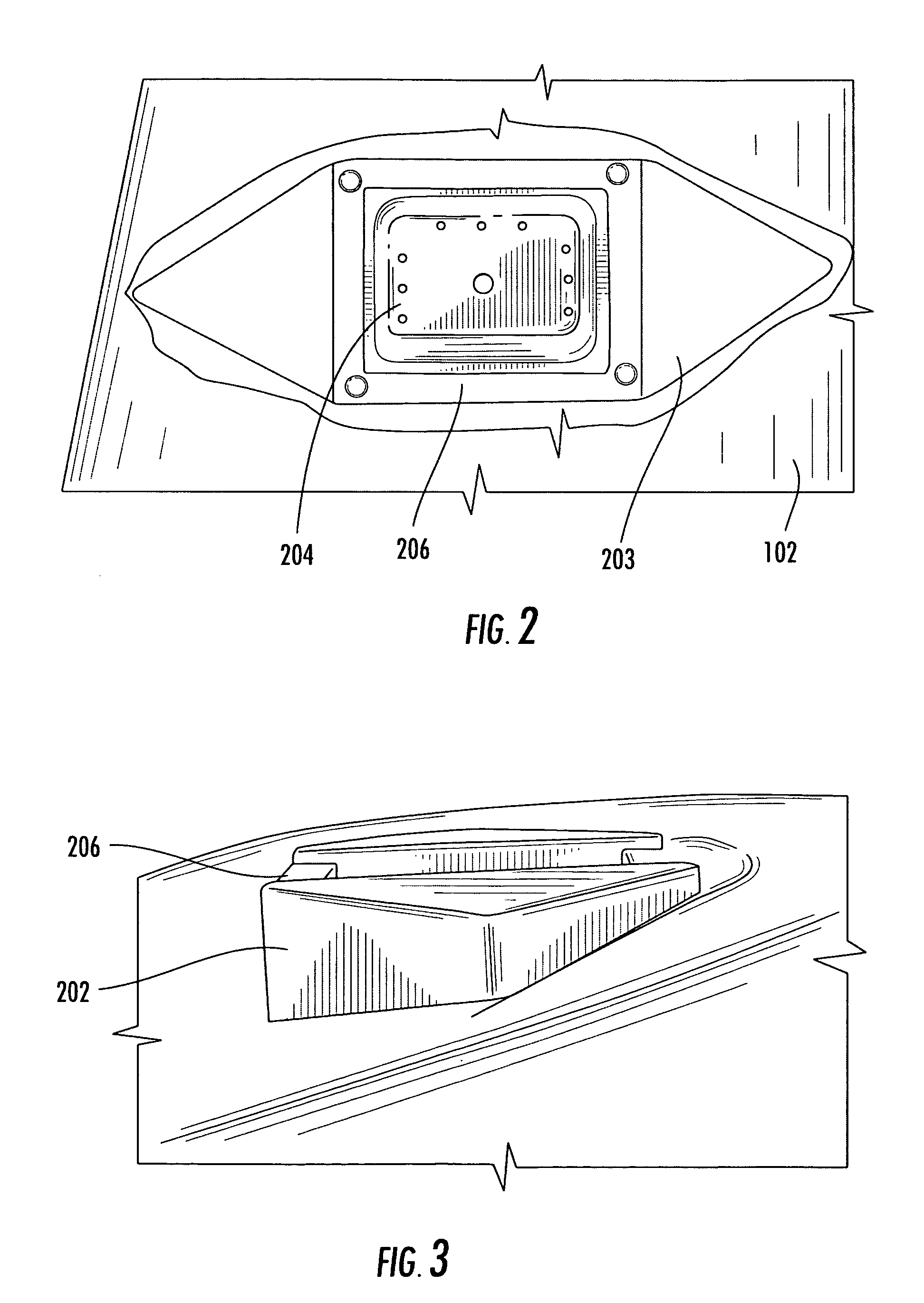
[0024]Referring to FIG. 2 there is shown a close up view of a portion of the vessel hull showing the transducer modular m...


PUM


Abstract

A vessel hull transducer modular mounting system enables transducers to be replaced and upgraded without necessitating the further modification of the hull and thus not necessitating the dry-docking of the vessel. A further feature includes the ability to reduce and dampen acoustic shock impact on the transducer. Another feature includes the ability to extend and retract the transducer which can operate in bottom scan, forward looking, side scan, searchlight, and sweep modes.

Description

CROSS REFERENCES TO RELATED APPLICATIONS[0001]This application claims the benefit under 35 U.S.C. 119(e) of U.S. Provisional Application Ser. No. 60 / 552,769, entitled Vessel Hull Transducer Modular Mounting System, filed on Mar. 12, 2004, and United States Provisional Application Ser. No. 60 / 660,225, entitled Vessel Transducer Modular Mounting System, filed on Mar. 10, 2005.FIELD OF INVENTION[0002]The present invention relates to vessel hulls and more particularly to the mounting of transducers.BACKGROUND OF THE INVENTION[0003]Transducers, such as acoustic transducers are employed by a vessel for mapping and locating. Transducers direct a number of streams of energy, such as sonar or other pulsed energy towards the bottom of the water while the vessel transverses the location. The transducer receives reflected signals from the water bottom, or an intervening object (such as fish, a diver, torpedo or submarine). The raw signal is translated and processed into a map of the water botto...

Claims


Application Information

Patent Timeline
IPC IPC(8): H04R1/02
CPCG01S7/521G10K11/006
Inventor SCHROEDER, TERRENCE K.
Owner SWCE
Why Eureka
Try Eureka