
Biasing arrangement for a pawl of a reversible ratchet-type wrench

a pawl and ratchet-type technology, which is applied in the direction of wrenches, friction clutches, clutches, etc., can solve the problems of increasing assembly time and manufacturing costs, adversely affecting appearance, and relatively difficult formation of cylindrical openings 34/b> that extend upward at an inclination

Inactive Publication Date: 2007-07-03
HU BOBBY
View PDF239 Cites 55 Cited by
  • Summary
  • Abstract
  • Description
  • Claims
  • Application Information

AI Technical Summary

Problems solved by technology

Yet, this increases the assembly time and the manufacture cost and adversely affects the appearance.
Nevertheless, formation of the cylindrical opening 34 that extends upward at an incline is relatively difficult.
In addition, formation of the cavity 16 having converging straight sides 17, 18 which diverge in the direction of the periphery of the rotatable member 14 requires expensive and accurate computer-numeric-control (CNC), which further results in an increase in the cost together with a low production rate.
Further, the resultant head structure is relatively weak and thus has a poor torque-bearing capacity.
In addition, the movement of the pawl 30′ for changing ratcheting direction is found unreliable, as it is achieved via transmission of the hook end 442′ of a spring 44′ attached to the shifting lever 40′.

Method used


Image

  • Biasing arrangement for a pawl of a reversible ratchet-type wrench
  • Biasing arrangement for a pawl of a reversible ratchet-type wrench
  • Biasing arrangement for a pawl of a reversible ratchet-type wrench

Examples


second embodiment

[0060]FIG. 7 illustrates a second embodiment in accordance with the present invention, wherein the gear wheel 20 is replaced by a drive member 70 having a drive column 73 with an engaging means 80 for releasably engaging with a socket (not shown). The drive member 70 includes an outer periphery having a plurality of teeth 71 for engaging with the ratchet teeth 41. An annular groove 731 is defined in a lower portion of the outer periphery of the drive member 70 for engaging with the C-clip 30, which is identical to that disclosed above. In addition, the drive member 70 includes a stub 72 on a top thereof, and the upper portion of the head 11 is modified to include an end wall 133 with an opening 134 for rotatably receiving the stub 72 of the drive member 70, thereby providing stable rotational movement for the drive member 70.

third embodiment

[0061]FIG. 8 illustrates a third embodiment in accordance with the present invention. It is noted that the biasing means (now designated by 90) in this embodiment includes a pin 91 having a receptacle 911 for receiving an end of the elastic element 92. Thus, the elastic element 92 is attached between an end wall (not labeled) defining the receptacle 911 of the pin 91 and an end wall (not labeled) defining the receptacle 521 of the switch member 50.

[0062]FIG. 9 illustrates a fourth embodiment in accordance with the present invention. It is noted that the biasing means 90 in the fourth embodiment is identical to that of the third embodiment, and the drive member 70 in the fourth embodiment is identical to that of the second embodiment.


PUM


Abstract

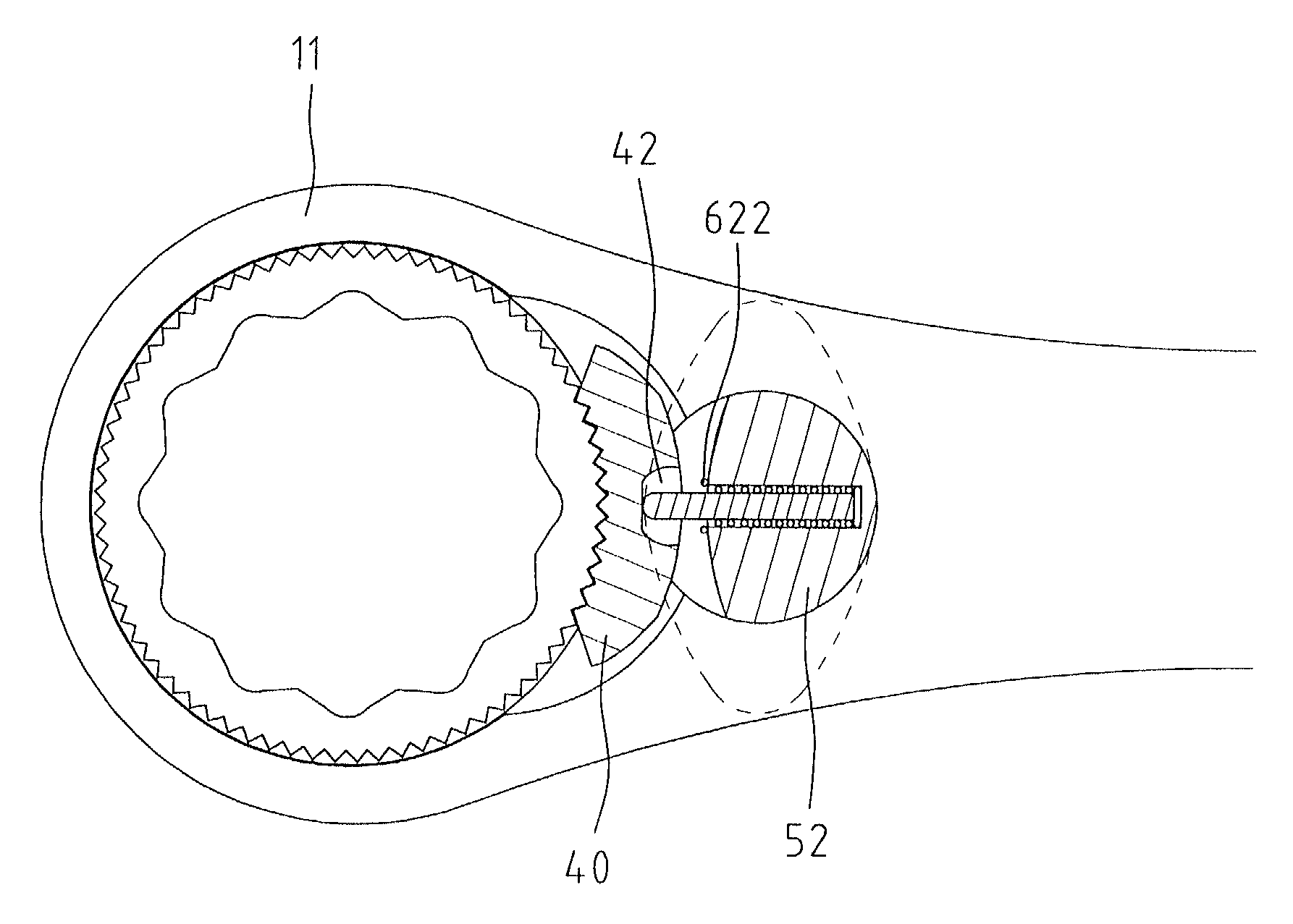
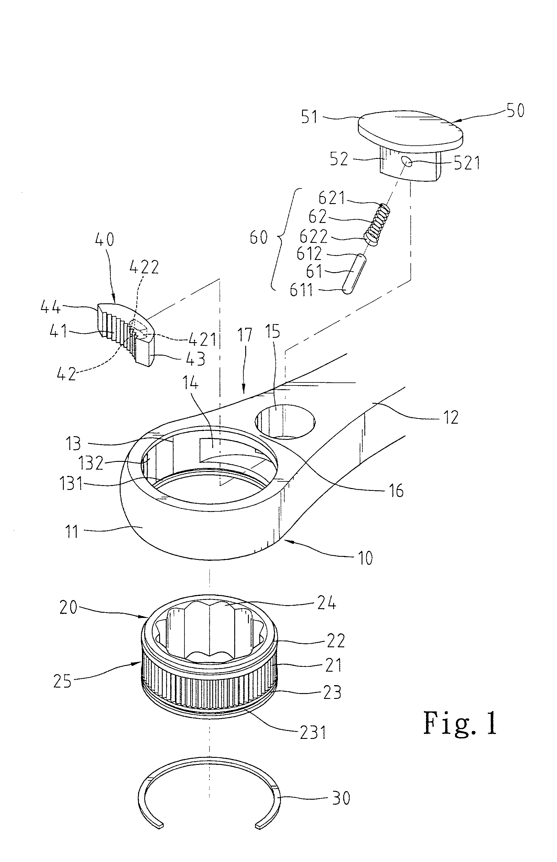
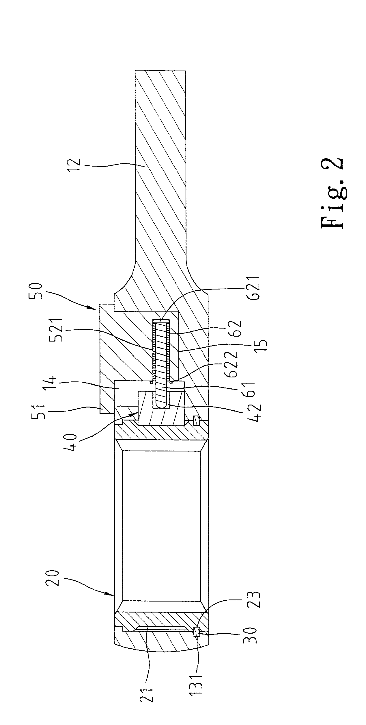
A reversible ratchet-type wrench includes a handle and a head extended from the handle and having a hole. A web is defined between the handle and the head, and a cavity is defined in the web and communicated with the hole. The web further includes a compartment having a first end communicated with the cavity and a second end communicated with outside, thereby leaving a bridge in the web. A drive member is rotatably mounted in the hole of the head. A pawl is mounted in the cavity and includes a first side with ratchet teeth for releasably engaging with teeth on an outer periphery of the drive member. A switch member includes a turn-piece for manual operation and an actuating plate extended from the turn-piece and rotatably received in the second end of the compartment of the head. The switch member is switchable between two positions for changing ratcheting direction of the drive member. A biasing arrangement is mounted in the cavity and between the pawl and the actuating plate for biasing the ratchet teeth of the pawl to engage with the teeth of the drive member.

Description

CROSS REFERENCE[0001]This application is a continuation of Ser. No. 09 / 541,193 filed Apr. 3, 2000, now U.S. Pat. No. 6,282,992.BACKGROUND OF THE INVENTION[0002]1. Field of the Invention[0003]The present invention relates to a biasing arrangement for a pawl of a reversible ratchet type wrench to provide reliable ratcheting. The present invention also relates to an improved head structure for a ratchet-type wrench to lower the manufacture cost.[0004]2. Description of the Related Art[0005]U.S. Pat. No. 2,957,377 issued to Hare on Oct. 25, 1960 discloses a reversible ratchet-type wrench comprising a body 10 having a handle 11 and a head 12. A cap 39 and an annular wall 44 are provided to the upper side and the lower side of the head 12, respectively. Yet, this increases the assembly time and the manufacture cost and adversely affects the appearance. A shifting lever 35 is retained in place by a spring 33 that is located in a cylindrical opening 34. Nevertheless, formation of the cylindr...

Claims


Application Information

Patent Timeline
Patent Type & Authority Patents(United States)
IPC IPC(8): B25B13/46
CPCB25B13/463
Inventor HU, BOBBY
Owner HU BOBBY
Features
  • Generate Ideas
  • Intellectual Property
  • Life Sciences
  • Materials
  • Tech Scout
  • Unparalleled Data Quality
  • Higher Quality Content
  • 60% Fewer Hallucinations
Learn More