
Pneumatic tool having pressure release device

a technology of releasing device and pneumatic tool, which is applied in the direction of positive displacement liquid engine, piston pump, portable drilling machine, etc., can solve the problems of rotor and fastener damage, tool extension or other tool parts of the tool, and the typical pneumatic tool

Inactive Publication Date: 2007-07-03
LIAO YU HUI
View PDF6 Cites 26 Cited by
  • Summary
  • Abstract
  • Description
  • Claims
  • Application Information

AI Technical Summary

Benefits of technology

"The present invention provides a pneumatic tool with a pressure releasing device for releasing air or pressure after a fastener has been tightly driven onto an object. The tool includes a housing with a conduit for receiving and guiding pressurized air to drive a rotor, and a driving shank for driving fasteners. A pressure releasing device is provided to release the air or pressure after the fastener is tightly driven. The driving shank includes a paddle for being frictionally driven by the container, and a spring member for biasing the paddle against the inner surface of the container. The housing includes a bore and a valve seat, and a piston for selectively blocking the valve seat. The container includes a receptacle for rotatably receiving the rotor, and a duct for partially receiving the pole. The pneumatic tool also includes a rod for adjusting the driving torque of the driving shank against the fastener. The tool includes a rotor with blades for engaging with the inner surface of the container."

Problems solved by technology

However, when or after the fasteners have been completely or tightly driven onto the objects to be fastened, or after a predetermined driving torque has been applied onto or against the fasteners or the tool extensions or other tool member, the pressurized air may still be or may continuously be supplied into the motor cylinder and may further rotate or to drive the rotor and the fasteners or the tool extensions or other tool member, such that the rotor and the fasteners or the tool extensions or other tool member may be damaged by the typical pneumatic tools.

Method used


Image

  • Pneumatic tool having pressure release device
  • Pneumatic tool having pressure release device
  • Pneumatic tool having pressure release device

Examples


Embodiment Construction

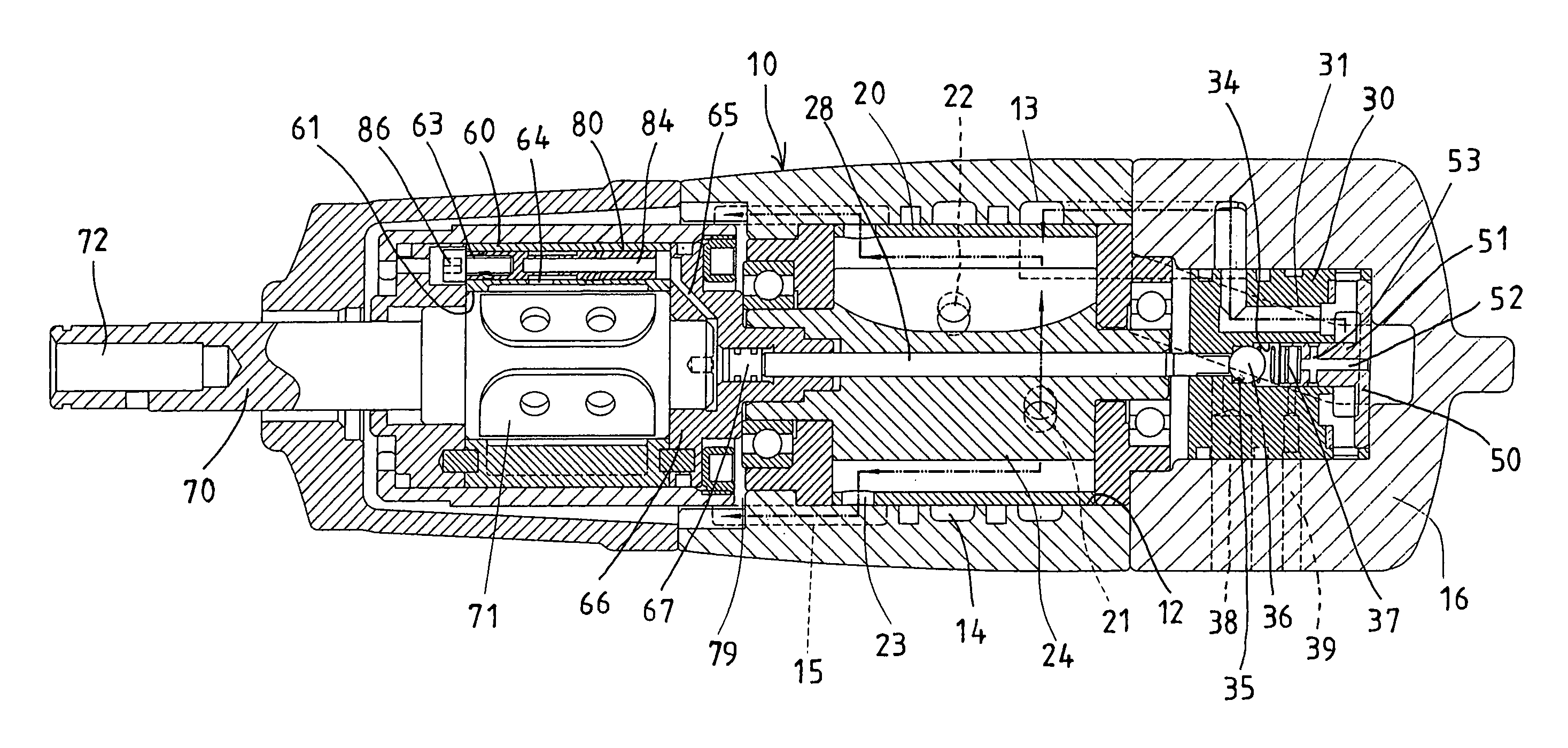
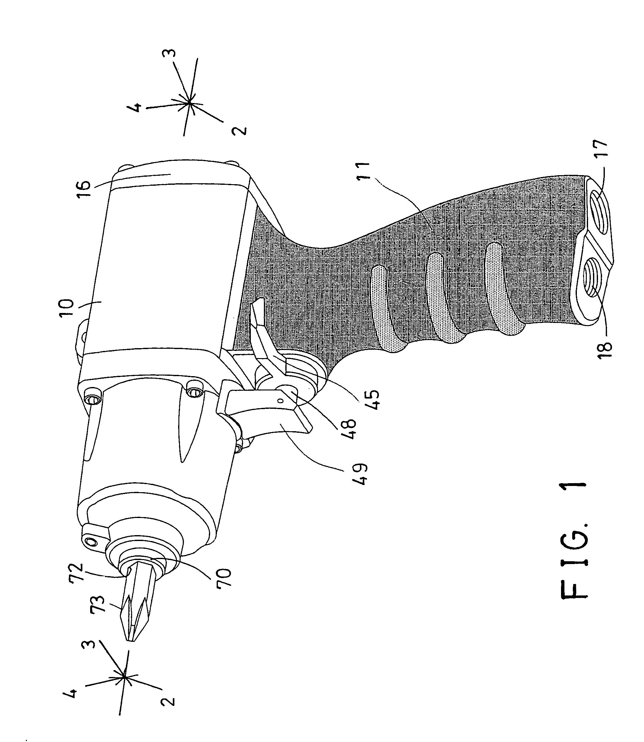
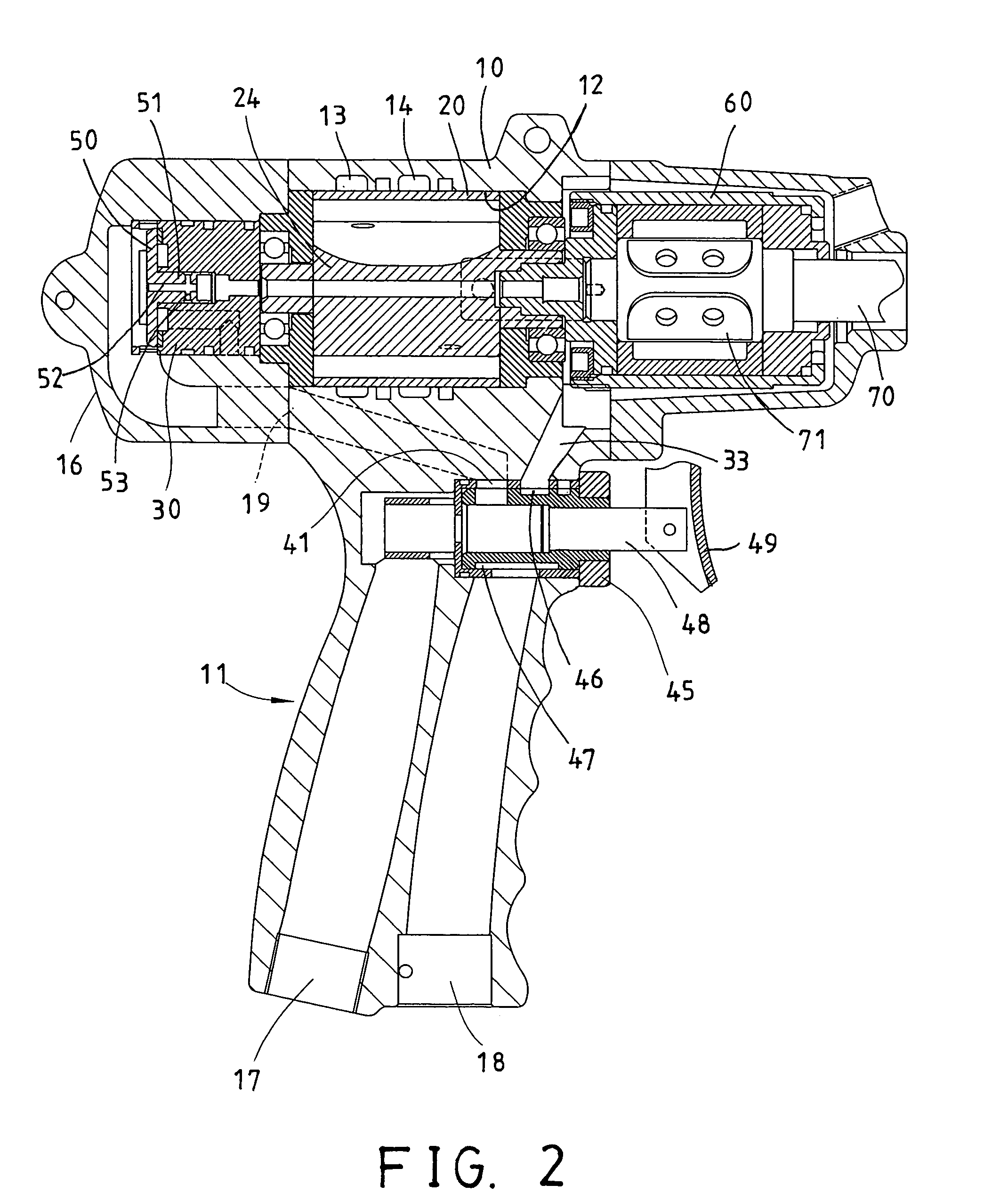
[0036]Referring to the drawings, and initially to FIGS. 1–7, a pneumatic tool in accordance with the present invention comprises a body member or a housing 10 including a handle 11 extended downwardly therefrom, for being grasped or held by the users, and including a chamber 12 formed therein, and one or more, such as two peripheral channels 13, 14 and a passage 15 formed therein and communicating with the chamber 12 thereof, for air flowing purposes.

[0037]The handle 11 includes a cap 16 attached to the rear portion thereof, for enclosing the chamber 12 thereof, and includes an inlet 17 formed therein, for coupling to such as a pressurized air reservoir, for receiving the pressurized air therefrom, and includes an outlet 18 formed therein, for releasing the pressurized air. The housing 10 includes a conduit 19 formed therein (FIG. 2) for selectively communicating with the inlet 17 of the handle 11, to allow the pressurized air to flow into the housing 10, such as to flow into the ca...


PUM

PropertyMeasurementUnit
pressureaaaaaaaaaa
forceaaaaaaaaaa
driving torqueaaaaaaaaaa

Abstract

A pneumatic tool includes a rotor rotatably received in a housing, a driving shank coupled to the rotor, for being rotated by the rotor and by a pressurized air and having one end for driving a fastener. A pressure releasing device may release the pressurized air after the fastener has been tightly threaded onto the object to be fastened. A fluid container is rotatably received in the housing and coupled to the rotor, for partially receiving the driving shank. The driving shank has one or more paddles for being frictionally driven by the container and by the fluid. A pole is slidably engaged through the rotor, and actuated to release the pressurized air when the fastener has been tightly threaded onto the object.

Description

BACKGROUND OF THE INVENTION[0001]1. Field of the Invention[0002]The present invention relates to a pneumatic driving tool, and more particularly to a pneumatic driving tool having a pressure releasing device for suitably releasing the air or the air pressure within the pneumatic driving tool, and for preventing the pneumatic driving tool to continuously drive the fasteners even after the fasteners have been completely or tightly driven onto the objects to be fastened.[0003]2. Description of the Prior Art[0004]Typical pneumatic tool comprise a fan device or a rotor rotatably received within a housing and including a shank extended out of the housing, for engaging with and for driving fasteners or tool extensions or other tool members, and an air inlet for receiving and guiding a pressurized air toward the rotor device, in order to rotate or to drive the rotor device and thus to drive the fasteners or the tool extensions or other tool members.[0005]For example, U.S. Pat. No. 3,827,834...

Claims


Application Information

Patent Timeline
Patent Type & Authority Patents(United States)
IPC IPC(8): B25D16/00B25D17/00B25D17/10B25B9/00B25B21/00B25B23/145F01C1/344F01C20/04F01C20/06F01C21/00F04B17/00F04B35/00
CPCB25B21/00B25B23/145F01C1/3446F01C20/04F01C20/06F01C21/008
Inventor LIAO, YU HUI
Owner LIAO YU HUI
Learn More