
Systems and methods for displaying images and processing work pieces

a technology of work pieces and systems, applied in the field of systems and methods for displaying images, can solve the problems of inefficient use of materials and time-consuming processes

Inactive Publication Date: 2007-07-10
LAP LASER
View PDF45 Cites 48 Cited by
  • Summary
  • Abstract
  • Description
  • Claims
  • Application Information

AI Technical Summary

Problems solved by technology

Such a process is time consuming, and may lead to inefficient use of material.

Method used


Image

  • Systems and methods for displaying images and processing work pieces
  • Systems and methods for displaying images and processing work pieces
  • Systems and methods for displaying images and processing work pieces

Examples


Embodiment Construction

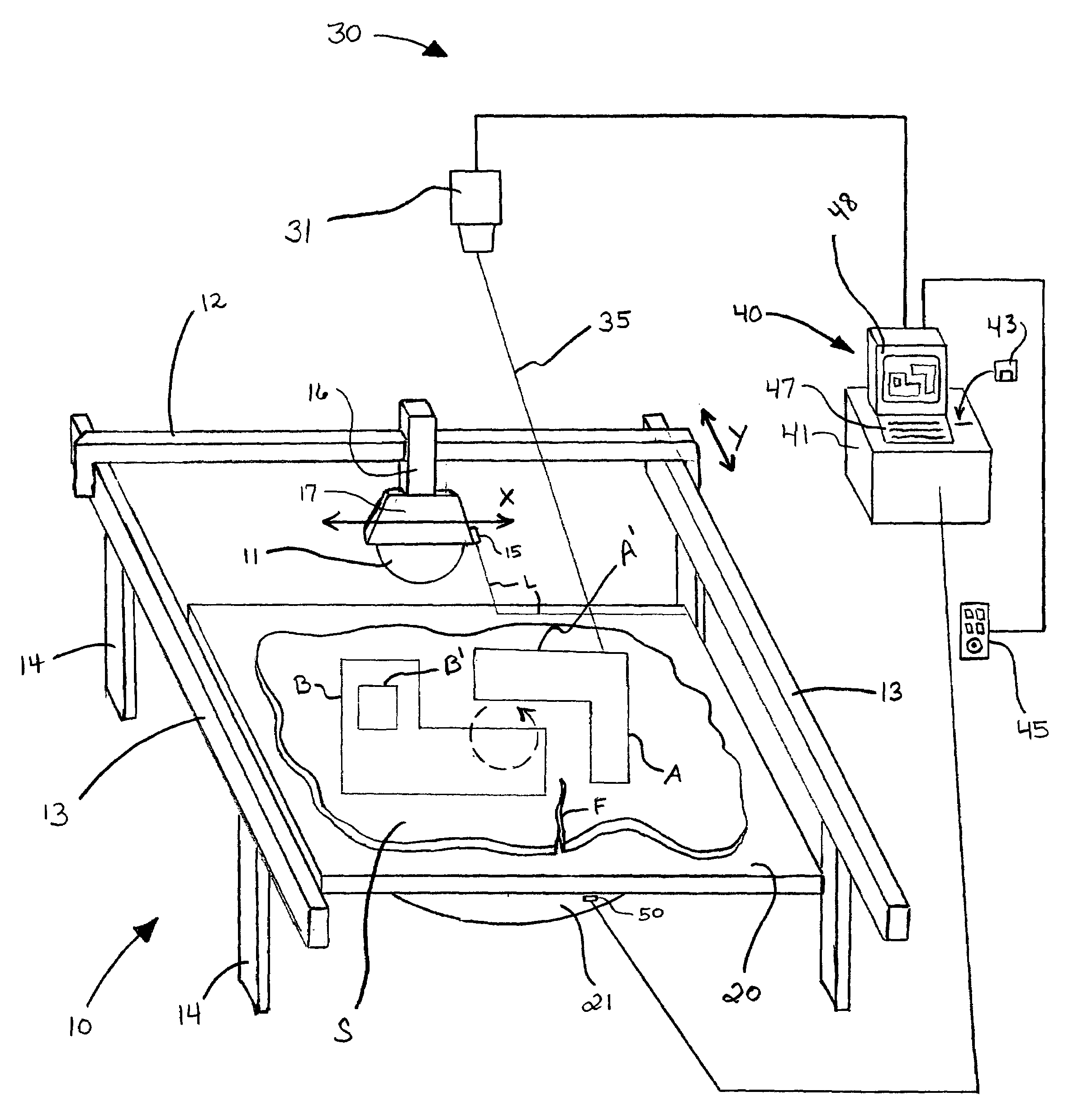
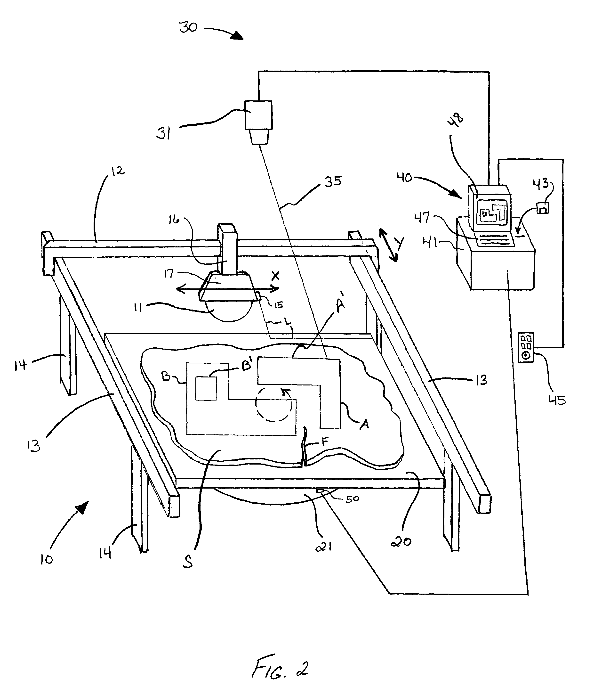
[0032]The present invention is directed to systems and methods for displaying images on a work piece or work surface using, for example, a laser projection system. The present invention also provides systems and methods for processing and / or assembling work pieces using the displayed images as a guide (e.g., as a template). By way of example, the displayed image may comprise a pattern defining the outline of structure to be machined (e.g., cut) from the work piece. While the following detailed description and accompanying drawings depict exemplary embodiments which may be used for cutting stone and similar materials, the scope of the present invention is not so limited.

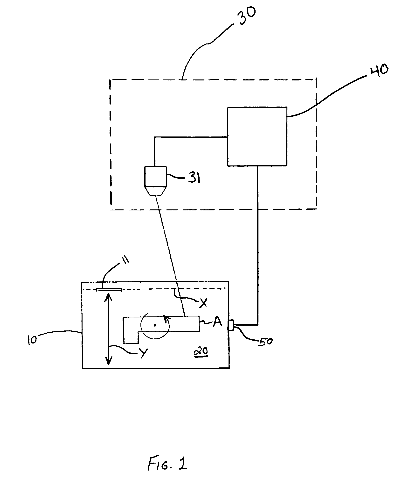
[0033]FIG. 1 is a schematic illustration of one exemplary embodiment of the present invention. The system of FIG. 1 comprises a work piece processing machine 10, a tool 11 associated with the processing machine for processing the work piece, and an optical projection system 30. Optical projection system 30 includes an...


PUM

PropertyMeasurementUnit
timeaaaaaaaaaa
shapeaaaaaaaaaa
structureaaaaaaaaaa

Abstract

A method of displaying an image on a work piece positioned on a movable work surface. A method of processing a work piece, as well as a method of displaying an image on a moveable work surface, is also provided. A system for machining a work piece in accordance with one or more images projected onto the work piece is also provided.

Description

CROSS-REFERENCES TO RELATED APPLICATIONS[0001]This Application claims the benefit under 35 U.S.C. § 119 of U.S. Provisional Application Ser. No. 60 / 550,670, filed Mar. 5, 2004, which is incorporated herein by way of reference.FIELD OF THE INVENTION[0002]The present invention relates to systems and methods for displaying images on a work piece or work surface, as well as systems and methods for processing work pieces using displayed image(s) as a guide. In one particular embodiment, the present invention provides systems and methods for displaying a pattern(s) on a work piece using a laser projector, and using the displayed pattern(s) as guide for processing the work piece (e.g., cutting a stone slab using the pattern(s) as a cutting guide or template).BACKGROUND OF THE INVENTION[0003]Many materials must be cut in accordance with one or more predetermined patterns. In order to cut these materials, the pattern is typically transferred to the material in a variety of manners. In some i...

Claims


Application Information

Patent Timeline
Patent Type & Authority Patents(United States)
IPC IPC(8): G01J1/20H01L27/00
CPCB28D1/043A43D95/14A43D8/16B23Q15/013G05B2219/36447B28B7/0017B28B17/00B28B7/0032G05B19/182
Inventor HOFMANN, KARSTEN
Owner LAP LASER
Learn More