Electromagnetic gap sub assembly

a sub-assembly and electric insulation technology, applied in the field of borehole telemetry, can solve the problems of reducing the overall drilling efficiency, not being able to rotate the drill string, and time-consuming, and achieve the effect of cost-effective and highly robust methods

Inactive Publication Date: 2007-08-07
WEATHERFORD TECH HLDG LLC
View PDF70 Cites 54 Cited by
  • Summary
  • Abstract
  • Description
  • Claims
  • Application Information

AI Technical Summary

Benefits of technology

[0013]This invention overcomes the problem of creating an electrical break in the drill string in a compact and cost effective yet highly robust method.

Problems solved by technology

This is time consuming and reduces overall drilling efficiency.
It also may not be possible to rotate the drill string with the wireline cable in the hole.
A drawback of the mud pulse technique is that the data transmission rates are very slow.
Transmission rates are limited by poor pulse resolution as pressure pulses attenuate along the borehole and by the velocity of sound within the drilling mud.
Further, while mud pulse systems work well with incompressible drilling fluids such as a water-based or an oil-based mud, mud pulse systems do not work well with gasified fluids or gases typically used in underbalanced drilling.
However, these coatings generally lack sufficient abrasion resistance when in contact with the abrasive rock cuttings and require frequent maintenance or replacement.
In addition, the composite coatings typically do not provide a significant beneficial effect to the bending or compressive strength of the design.
Additionally, the known gap sub assembly is expensive to manufacture.
Furthermore, the known gap sub assembly is bulky and cumbersome to employ during a drilling operation.

Method used


Image

  • Electromagnetic gap sub assembly
  • Electromagnetic gap sub assembly
  • Electromagnetic gap sub assembly

Examples


Embodiment Construction

[0029]Embodiments of the present invention generally provide a method and an apparatus for use in an EM telemetry system. For ease of explanation, the invention will be described generally in relation to drilling directional wells, but it should be understood, however, that the method and the apparatus are equally applicable in other telemetry applications. Furthermore, it should be noted that the principles of the present invention are applicable not only during drilling, but throughout the life of a wellbore such as logging, testing, completing, and producing the well.

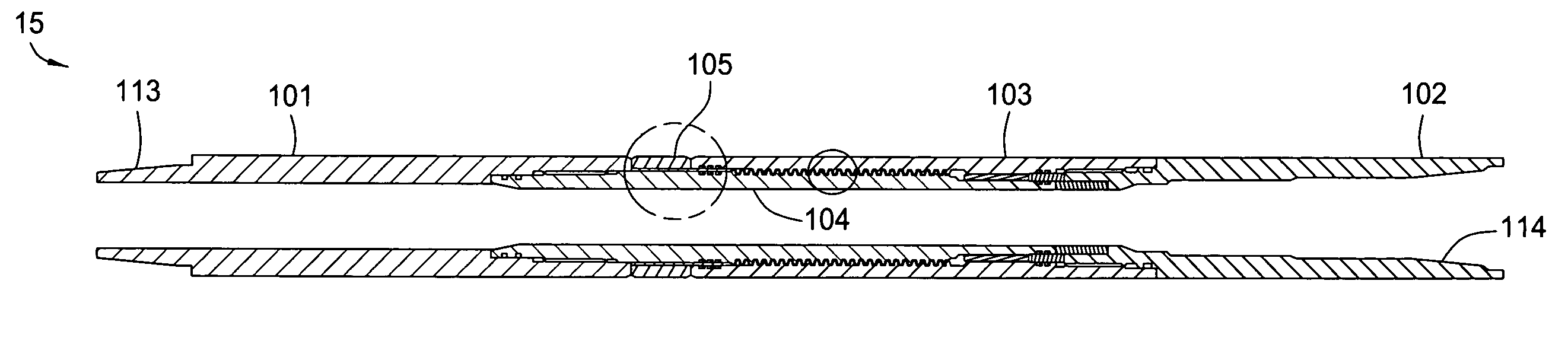
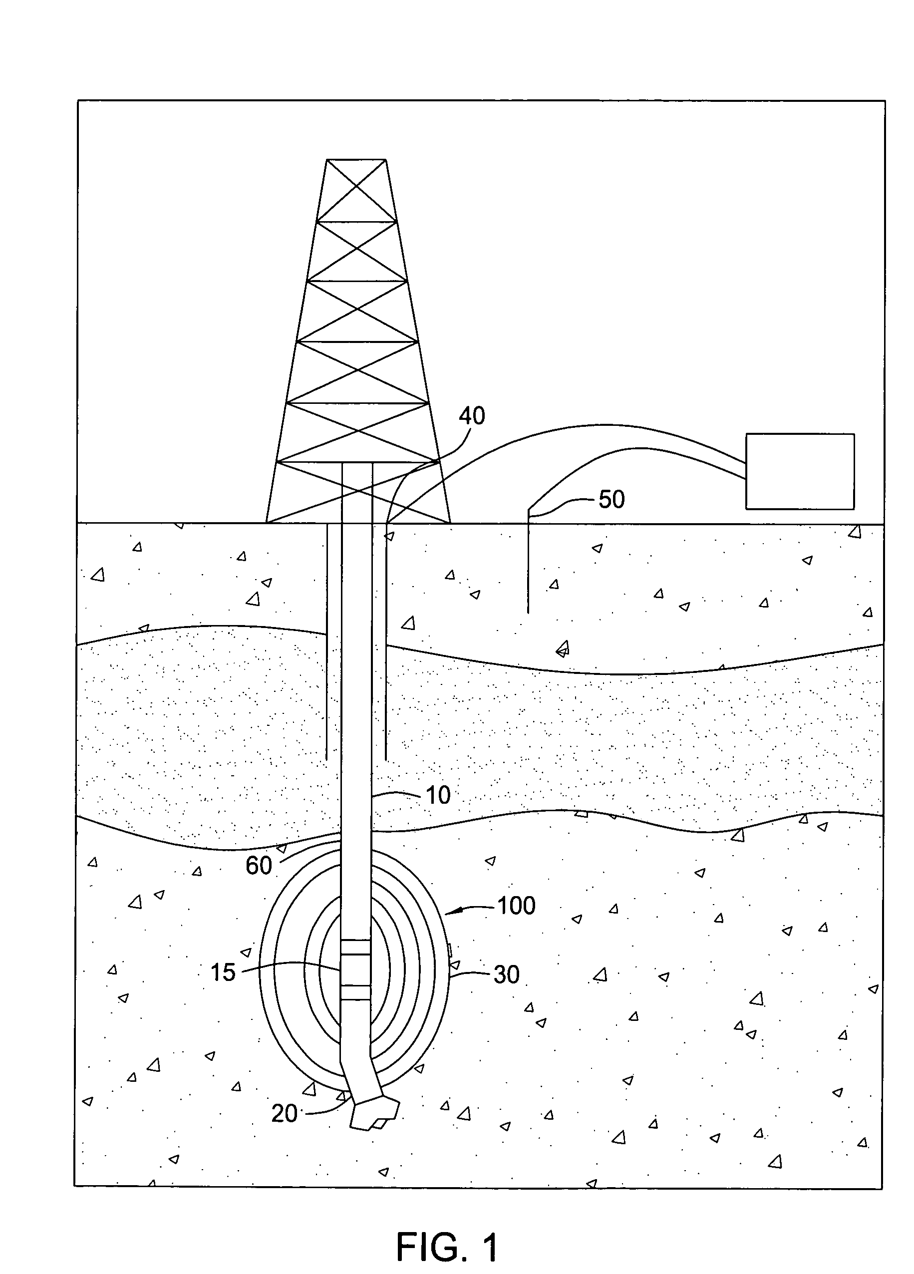
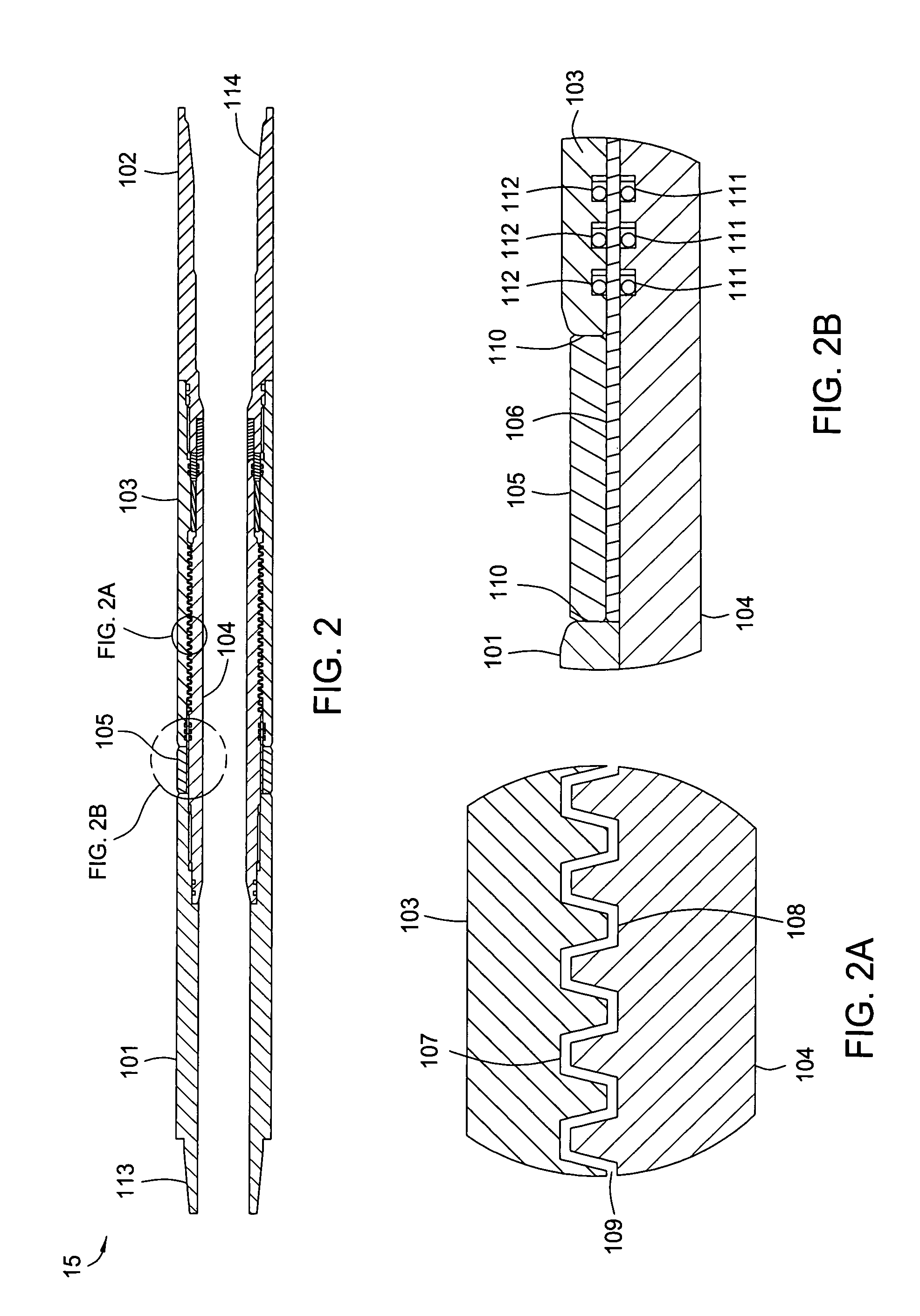
[0030]FIG. 1 illustrates a drilling rig structure 40 and an EM telemetry system 100 utilizing a gap sub assembly 15 of the present invention. Generally, the EM telemetry system 100 may be used as a method to generate and receive the electromagnetic waves downhole. The method typically involves creating an electrical break between an upper section 10 and a lower section 20 of a drill string 60 to form a large antenna....


PUM


Abstract

A compact, robust, wear resistant, and high performance electrically insulating gap sub for use with borehole EM Telemetry is disclosed. In one embodiment, the gap sub may include an externally threaded mandrel separated from an internally threaded housing by a dielectric material. Additionally, some embodiments may include an external gap ring for separating the upper and lower electrical halves of the sub which offers structural support, acts as the primary external seal, and provides an abrasion resistant non-conductive length on the exterior. Some embodiments may include torsion pins to prevent the possible unscrewing of the dielectric filled threaded sections should the dielectric material become damaged or weakened.

Description

CROSS-REFERENCE TO RELATED APPLICATIONS[0001]This application claims priority to U.S. Provisional Patent Application Ser. No. 60 / 491,569, filed Jul. 31, 2003.[0002]This application is a continuation-in-part of U.S. patent application Ser. No. 10 / 744,683, filed Dec. 23, 2003. U.S. patent application Ser. No. 10 / 744,683 has issued as U.S. Pat. No 7,093,680. U.S. patent application Ser. No. 10 / 744,683 is a continuation of U.S. patent application Ser. No. 10 / 161,310, filed Jun. 3, 2002. U.S. patent application Ser. No. 10 / 161,310 has issued as U.S. Pat. No. 6,672,383. U.S. patent application Ser. No. 10 / 161,310 is a divisional of U.S. patent application Ser. No. 09 / 777,090, filed on Feb. 5, 2001. U.S. patent application Ser. No. 09 / 777,090 has issued as U.S. Pat. No. 6,405,795. U.S. patent application Ser. No. 09 / 777,090 is a divisional of U.S. patent application Ser. No. 08 / 981,070, filed Dec. 10, 1997. U.S. patent application Ser. No. 08 / 981,070 has issued as U.S. Pat. No. 6,209,632. ...

Claims


Application Information

Patent Timeline
Patent Type & Authority Patents(United States)
IPC IPC(8): E21B17/02E21B47/00E21B17/00E21B47/01F16L25/02
CPCE21B17/003E21B47/011F16L25/021E21B47/017
Inventor DOPF, TONYLOGAN, DEREK WILLIAMCAMWELL, PAUL LEONARDNERO, MICHAELHORST, CLEMENS L.SMALLWOOD, ROBERT E.
Owner WEATHERFORD TECH HLDG LLC
Why Eureka
Try Eureka