Reflex-ported folded horn enclosure

a horn enclosure and retractable technology, applied in the field of frontloaded horn enclosures, can solve the problems of reducing the possibility of producing standing waves, presenting a relatively small footprint for its performance capabilities,

Inactive Publication Date: 2007-08-07
MOORE DANA A
View PDF19 Cites 15 Cited by
  • Summary
  • Abstract
  • Description
  • Claims
  • Application Information

AI Technical Summary

Benefits of technology

[0012]It is an object of the present invention to provide substantially the same levels of performance and efficiency as in the previously cited examples while providing access to the horn throat from the top of the cabinet.
[0014]It is a further object of the present invention to provide an increased low frequency response by the incorporation of a reflex or ducted porting mechanism into the back chamber to utilize the radiation from the back of the driver in an additive manner to the reduced output from the horn below its respective low frequency cutoff.
[0016]The current invention also provides the advantage of presenting an appropriate elevation for the deployment of midrange and high frequency units, in particular, this aspect is more important for domestic use to achieve a homogenous sound wave front for the average seated listener. It is accepted practice that the height for midrange and high frequency horn units to be placed is approximately 35 to 44 inches in height from the floor for optimum presentation in domestic use. This arrangement is made more beneficial when used in a multi-channel role where it is preferred that the relative height of the high frequency units involved are aligned in the same approximate horizontal plane so as to produce a consistent presentation of the sound field to the seated listeners.

Problems solved by technology

This example features a simple design and additionally presents a relatively small footprint for its performance capabilities, which is substantially similar to the previously cited example.
It is also well known that the bifurcation of the respective horn at the throat provides for the smallest horn channel dimensions to be employed and for the folds to occur relatively close to the throat, which reduces the possibility of producing standing waves.

Method used


Image

  • Reflex-ported folded horn enclosure
  • Reflex-ported folded horn enclosure
  • Reflex-ported folded horn enclosure

Examples


Embodiment Construction

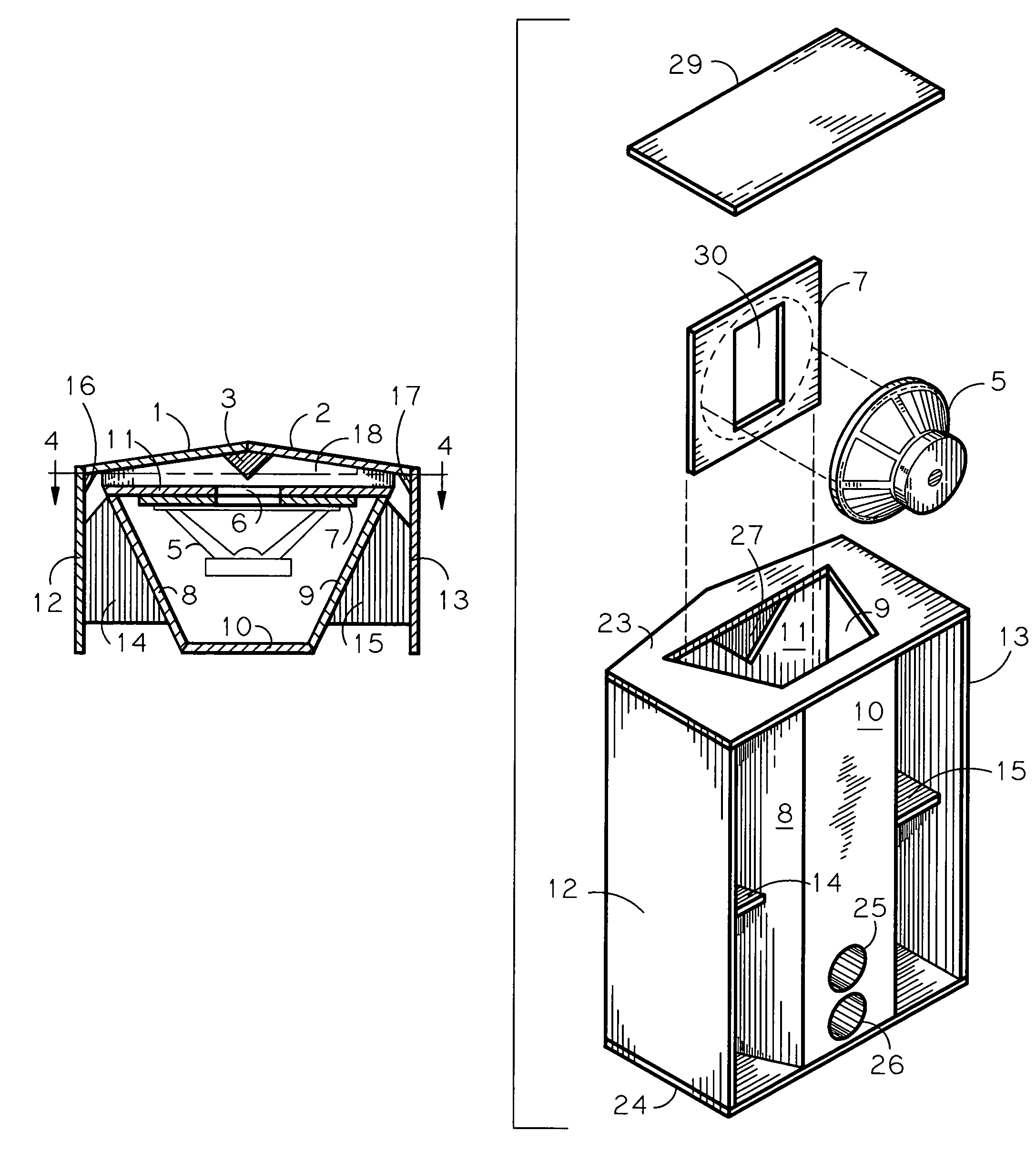
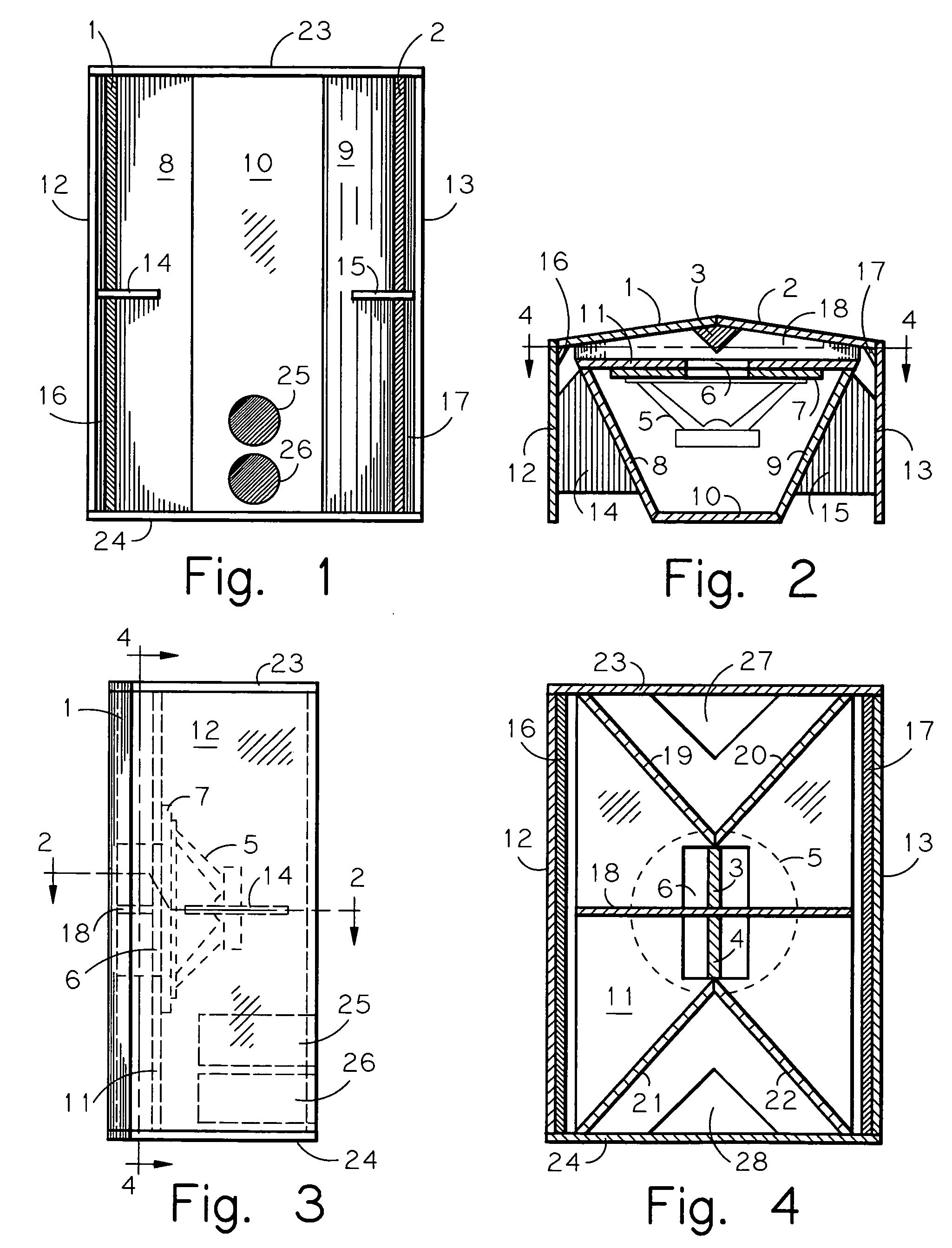
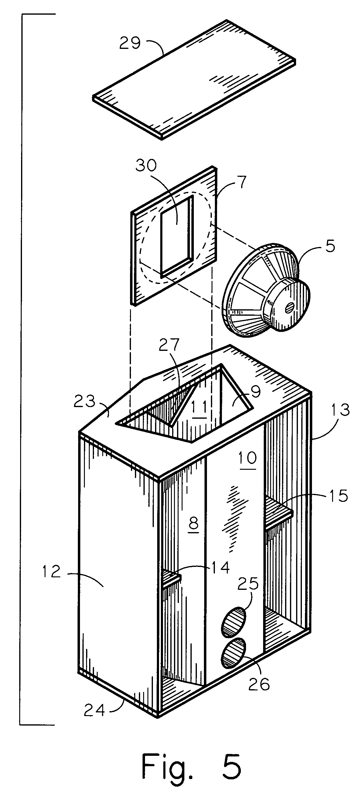
[0023]Referring to FIG. 1, the present invention embodiment is disclosed as seen from the front, where the overall horn mouth cross-sectional area is approximately 4 square feet. The ducted reflex ports 25, 26 contain an equivalent volume of approximately one-half of the overall mouth area. The selected port volume can be altered to accomplish frequency tuning based on the requirements of the application and respective horn driver employed. It is desirable to tune the ports to achieve a response of approximately 32 Hz.

[0024]Referring to FIG. 2, the present invention contains a trapezoidal back chamber formed from parts 8, 9, 10, 11 which create a vertically oriented column which is sealed against air leaks except for the top panel 23 access cutout and throat cavity opening 6. The throat cavity opening 6 exists on the back-facing baffle 11 portion of the back chamber and is configured to accept and mount a driver mounting board 7 to the baffle opening 6 in a manner common in the pres...


PUM


Abstract

A low frequency exponential / hyperbolic hybrid folded horn enclosure intended for use in proximity with at least one planar surface, such as a floor, ceiling, or wall, with access to the horn throat from the top of the enclosure. The horn is bifurcated at the throat and folds horizontally around a central trapezoid-shaped vertical back chamber which is reflex ported for enhanced low frequency response below the frequency cutoff of the horn. The back chamber outer sides define part of the horn channel, resulting in a relatively simple structure with a small footprint and no void internal space. The throat exponential expansion cross-sectional area is consistently maintained while the proportions of the throat channels are elongated to the height of the enclosure.

Description

CROSS REFERENCE TO RELATED APPLICATIONS[0001]Not ApplicableSTATEMENT REGARDING FEDERALLY SPONSORED RESEARCH OR DEVELOPMENT[0002]Not ApplicableREFERENCE TO SEQUENCE LISTING, A TABLE, OR A COMPUTER PROGRAM LISTING COMPACT DISK APPENDIX[0003]Not ApplicableBACKGROUND OF THE INVENTION[0004]The present invention relates to loudspeaker enclosures of the low frequency exponential folded horn type. More specifically, it relates to front-loaded horn enclosures that are reflex ported and are intended for use in close proximity to at least one planar surface, such as a floor, ceiling or wall.[0005]With the advent of the “Home Theatre” multi-channel market, there is a potential economic avenue for relatively large loudspeakers whose performance approaches the overall sound quality as might be found in commercial theatres. The use of horn loudspeaker enclosures provides the relative quality and the equivalent sound pressure levels that would also be associated with a commercial theatre experience...

Claims


Application Information

Patent Timeline
Patent Type & Authority Patents(United States)
IPC IPC(8): G10K11/02G10K11/20H04R1/34H04R1/38
CPCH04R1/30
Inventor MOORE, DANA A.
Owner MOORE DANA A
Why Eureka
Try Eureka