Ion transport apparatus and mass spectrometer using the same

a mass spectrometer and ion transport technology, applied in the direction of electron/ion optical arrangement, particle separator tube details, separation process, etc., can solve the problems of high device cost and difficulty in reducing related cost, and achieve the same level of ion-trapping and ion-transporting efficiency, simplify the electrode structure, and reduce the effect of system cos

Inactive Publication Date: 2016-06-30
SHIMADZU CORP
View PDF2 Cites 8 Cited by
  • Summary
  • Abstract
  • Description
  • Claims
  • Application Information

AI Technical Summary

Benefits of technology

[0044]According to the present invention, it is possible create an ion transport apparatus which uses fewer electrodes than the conventional radio-frequency carpet, ion funnel or similar apparatus and yet can achieve the same levels of ion-trapping and ion-transporting efficiencies. Therefore, for example, the system cost can be reduced by simplifying the electrode structure. Alternatively, the ion-trapping and ion-transporting efficiencies can be improved instead of simplifying the electrode structure.
[0045]With the mass spectrometer according to the present invention, for example, the sensitivity of the analysis can be improved by increasing the amount of ions to be subjected to the mass spectrometry.

Problems solved by technology

Therefore, it is difficult to reduce the related cost, and the device cost also tends to be high.
This requirement poses various challenges in creating a small-sized apparatus or changing the structure of the apparatus.

Method used


Image

  • Ion transport apparatus and mass spectrometer using the same
  • Ion transport apparatus and mass spectrometer using the same
  • Ion transport apparatus and mass spectrometer using the same

Examples


first embodiment

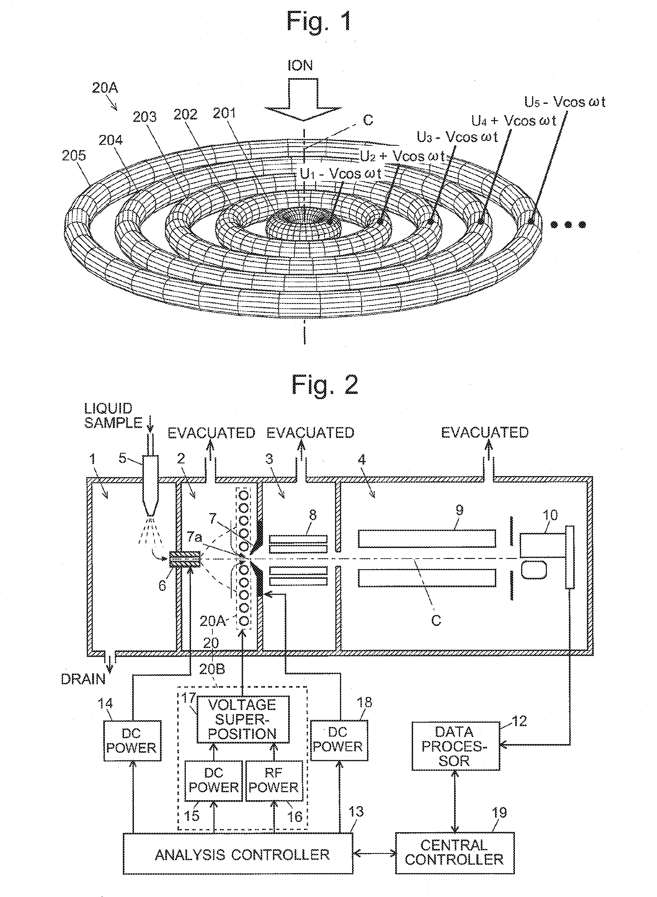
[0068]An electrospray ionization mass spectrometer, which is a mass spectrometer using one embodiment of the ion transport apparatus according to the present invention, is described. FIG. 2 is a schematic configuration diagram of the electrospray ionization mass spectrometer of the first embodiment.

[0069]The apparatus shown in FIG. 2 has the configuration of a multistage differential pumping system in which the degree of vacuum is increased in a stepwise manner in the traveling direction of the ions by providing two intermediate vacuum chambers 2 and 3 between the ionization chamber 1 (maintained at substantially atmospheric pressure) to the analysis chamber 4 (maintained at a high degree of vacuum), with the first intermediate vacuum chamber 2 maintained at a low degree of vacuum and the second intermediate vacuum chamber 3 maintained at an intermediate degree of vacuum between the first intermediate vacuum chamber 2 and the analysis chamber 4. Within the ionization chamber 1, a sa...

second embodiment

[0091]Various other embodiments of the mass spectrometer using the radio-frequency carpet with the configuration described in the first embodiment are described. FIG. 9 shows the configuration of the relevant section of a mass spectrometer as the second embodiment of the present invention.

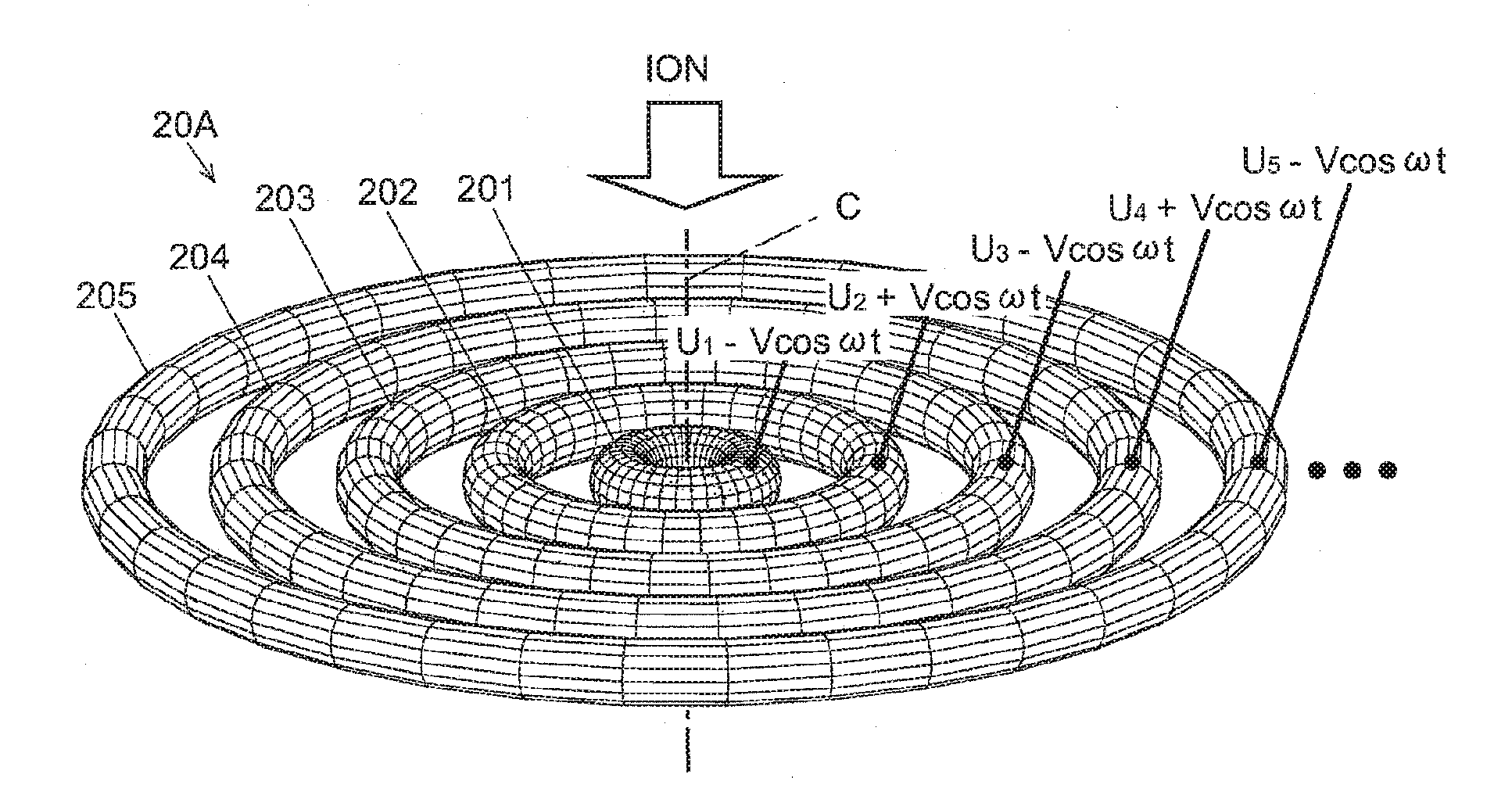
[0092]In the mass spectrometer of the first embodiment, the central axis of the heated capillary 6, that of the electrode group 20A constituting the radio-frequency carpet 20, and that of the ion-passing hole 7a are arranged on the same straight line. The mass spectrometer of the second embodiment has the “off-axis” configuration in which the central axis C1 of the heated capillary 6 is displaced from the central axis C2 of the ion-passing hole 7a by predetermined distance d. The central axis of the electrode group 20A of the radio-frequency carpet 20 lies on the same straight line as the central axis C2 of the ion-passing hole 7a. In general, an ion optical system having such an off-axis configura...

third embodiment

[0093]FIG. 10 shows the configuration of the relevant section of a mass spectrometer as the third embodiment of the present invention. Unlike the mass spectrometer of the second embodiment in which the central axis C1 of the heated capillary 6 is parallel to the central axis C2 of the ion-passing hole 7a, the central axis C1 of the heated capillary 6 in the third embodiment extends obliquely at angle θ to the central axis C2 of the ion-passing hole 7a. The radio-frequency carpet 20 used in this embodiment can efficiently trap ions without being significantly affected by the incident angle of the ions. Therefore, it can efficiently collect the target ions can and send them to the subsequent stage even if the incident direction of the ions is oblique as in this example.


PUM


Abstract

Within an intermediate vacuum chamber next to an ionization chamber maintained at atmospheric pressure, an electrode group of a radio-frequency carpet composed of a plurality of concentrically arranged ring electrodes is placed before a skimmer, with its central axis coinciding with that of an ion-passing hole. Each ring electrode has a circular radial sectional shape. Radio-frequency voltages with mutually inverted phases are applied to the ring electrodes neighboring each other in the radial direction. Additionally, a different level of direct-current voltage is applied to each ring electrode to create a potential which is sloped downward from the outer ring electrode to the inner ring electrode. The circular cross section of the electrode produces a steep pseudo-potential near the electrode and thereby increases the repulsive force which acts on the ions to repel them from the electrode.

Description

TECHNICAL FIELD[0001]The present invention relates to an ion transport apparatus for transporting ions while trapping them, and more specifically, to an ion transport apparatus suitable for a mass spectrometer including an ion source for ionizing a sample in an atmosphere having a comparatively high level of gas pressure which is close to atmospheric pressure, such as an electrospray ionization mass spectrometer, atmospheric pressure chemical ionization mass spectrometer, and radio-frequency inductively coupled plasma ionization mass spectrometer. It also relates to a mass spectrometer using such an ion transport apparatus.BACKGROUND ART[0002]In a mass spectrometer using an atmospheric pressure ion source, such as an electrospray ionization (ESI), atmospheric pressure chemical ionization (APCI) or atmospheric pressure photoionization (APPI), the atmosphere within the ionization chamber is maintained at substantially atmospheric pressure, whereas the atmosphere within the analysis ch...

Claims


Application Information

Patent Timeline
Patent Type & Authority Applications(United States)
IPC IPC(8): H01J49/06H01J49/40H01J49/00
CPCH01J49/063H01J49/401H01J49/005H01J49/062
Inventor NISHIGUCHI, MASARUIMAZU, AKIKOSAKAE, HIROKI
Owner SHIMADZU CORP
Why Eureka
Try Eureka