
Cleaning and/or inspecting robot for hazardous environments including catalyst removal

Active Publication Date: 2008-10-14
QUANTA ASSOC
View PDF9 Cites 14 Cited by
  • Summary
  • Abstract
  • Description
  • Claims
  • Application Information

AI Technical Summary

Benefits of technology

[0007]Another objective is to reduce “inert man hours” by employing a robot to perform routine vacuuming and inspection tasks normally performed by vessel entry technicians with the goal being to reduce inert man hours by 20%-50% while maintaining the same level of productivity and efficiency. It is believed that humans will still be needed to perform and complete final operations.

Problems solved by technology

An unfortunate byproduct of these chemical reactions is the accumulation of iron sulfides and / or other hazardous chemicals (such as arsenic) on the catalyst itself.
Iron sulfides are pyrophoric by nature, meaning they burn with exposure to air.
As such, the combination of hydrocarbons from the refining process, the presence of pyrophoric materials, and oxygen create a volatile “Fire Triangle” combination which can lead to a fire or explosion.
Of course, humans cannot live without oxygen so a life support system is required for entry into these confined spaces.
These “inert, IDLH entries” are a cause for great concern at virtually every refinery or petrochemical facility because a catastrophic life support system failure may or could result in a fatality.

Method used


Image

  • Cleaning and/or inspecting robot for hazardous environments including catalyst removal
  • Cleaning and/or inspecting robot for hazardous environments including catalyst removal
  • Cleaning and/or inspecting robot for hazardous environments including catalyst removal

Examples


Embodiment Construction

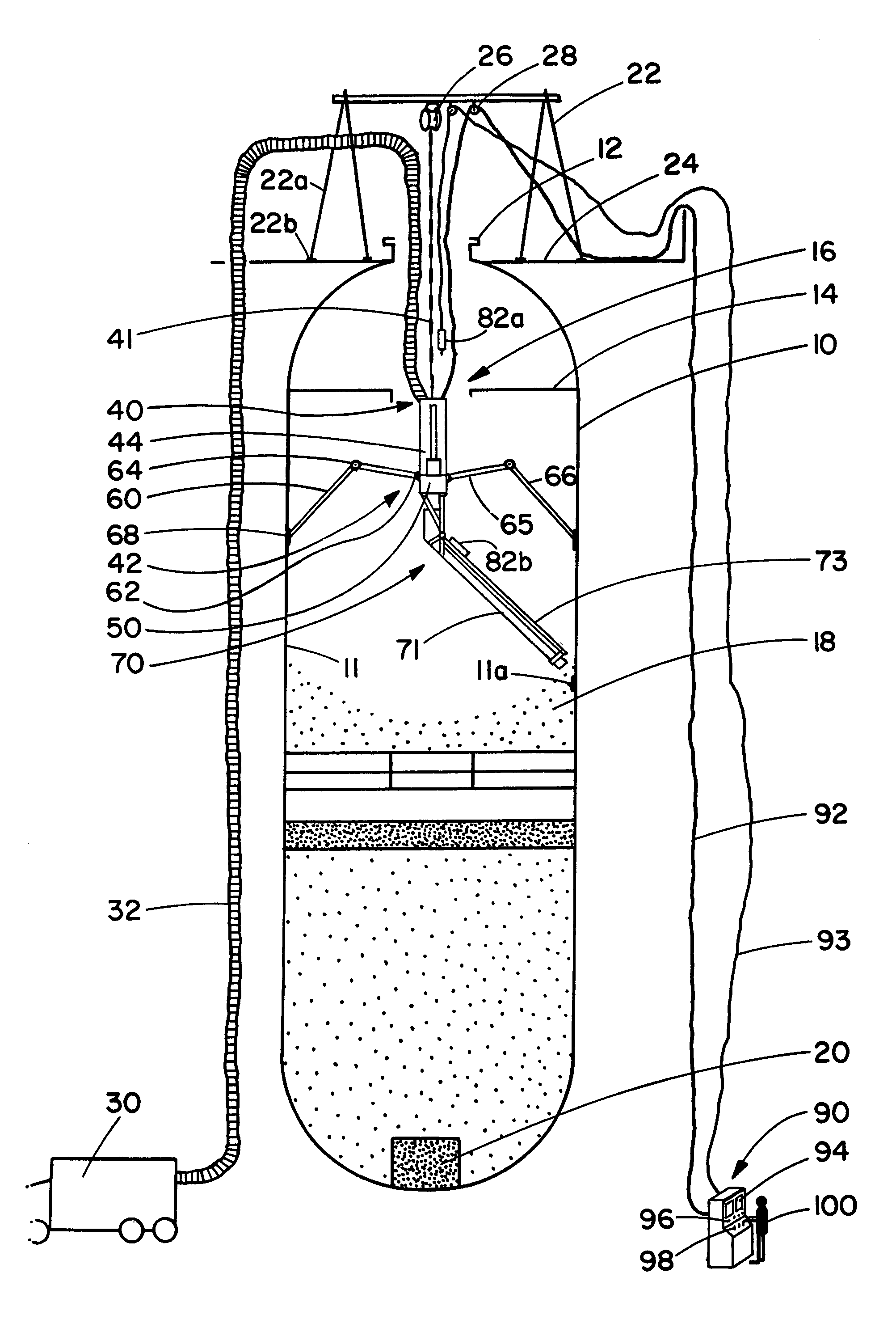
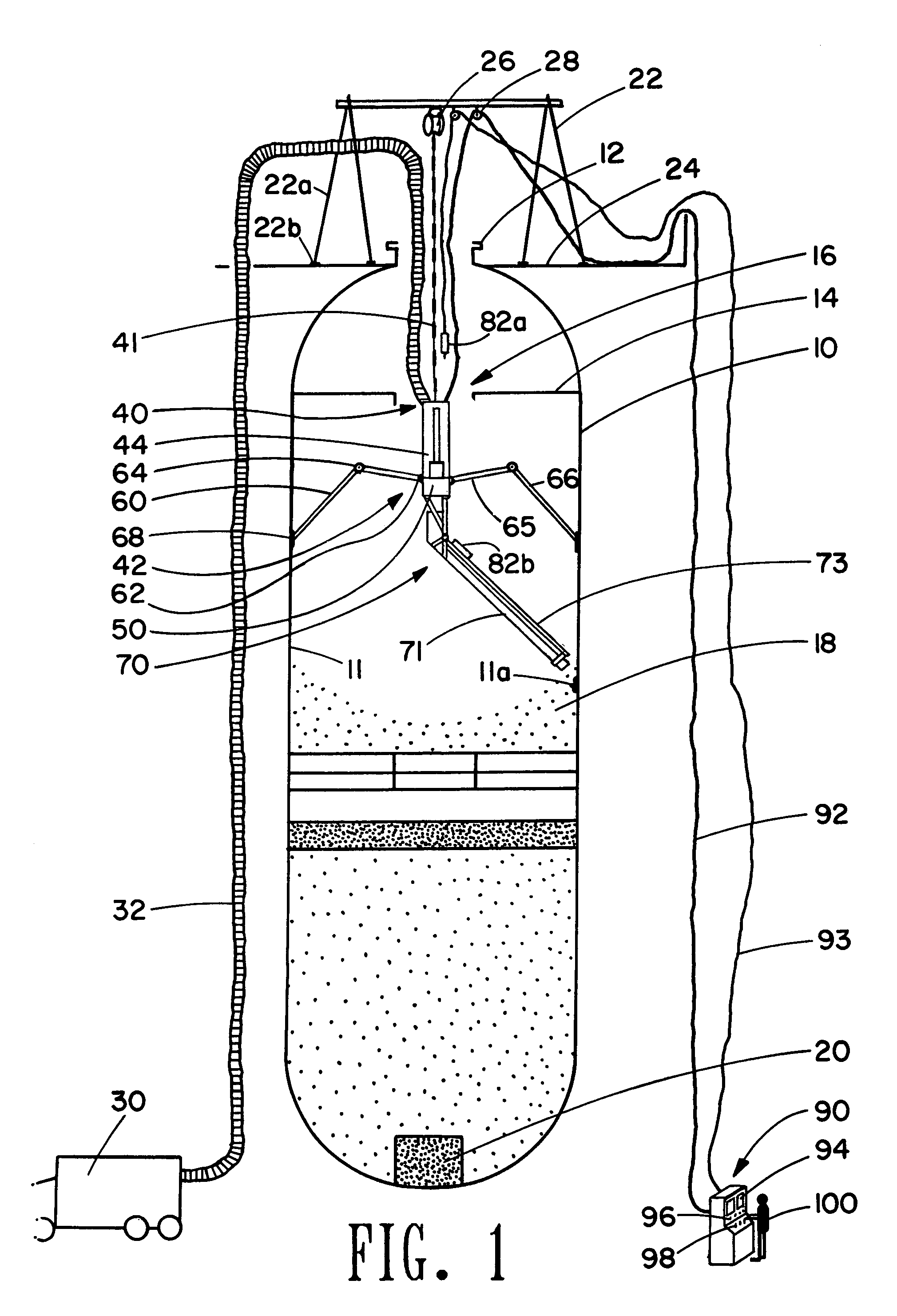
[0021]Referring to FIG. 1, a typical reactor vessel 10 is shown. The reactor vessel 10 has an entry manway 12, trays 14 with tray manways 16, catalyst 18 (which, as depicted, is to be removed), and an outlet screen 20 leading to a line out (not shown). An A-frame 22 is mounted on a platform 24 located near the top of the reactor vessel 10. A hoist system 26 and pulley 28 are mounted on the A-frame 22. The A-frame 22 may have legs 22a with vulcanized rubber pads 22b (between the legs 22a and the platform 24).

[0022]A vacuum source 30 which may be mobile is placed exterior to the reactor vessel 10. A vacuum line / tube 32 runs from the vacuum source 30 into the reactor vessel 10 and connects to a robotic device 40. The vacuum line 32 preferably runs into the main body 42 of the robotic device 40. The vacuum line 32 could be attached to the A-frame 22 with a hoist and pulley (not shown) mounted above the reactor vessel 10. The vacuum line 32 may, for example but without limitation, be mad...


PUM


Abstract

A vacuum line connected to a robotic device is run into a reactor vessel. The robotic device has a rotating body, a cleaning arm, and stabilizing arms to stabilize the robotic device within the reactor vessel. The robotic device may be controlled / monitored from a remote control station in communication with the robotic device.

Description

CROSS-REFERENCE TO RELATED APPLICATIONS[0001]This application claims the benefit of U.S. provisional application No. 60 / 436,121 filed Dec. 23, 2002.REFERENCE TO A MICROFICHE APPENDIX[0002]Not applicable.STATEMENTS REGARDING FEDERALLY SPONSOR RESEARCH OR DEVELOPMENT[0003]Not applicable.BACKGROUND OF THE INVENTIONDescription of the Related Art[0004]Reactor vessels are typically twenty to one hundred thirty feet in height and six to sixteen feet in diameter. These reactor vessels typically contain the catalyst and support materials to effect the chemical reactions necessary to convert crude oil or other feedstock material into desired products such as gasoline and diesel fuel. Following chemical reactions, spent catalyst is cleaned / removed from the reactor vessel by humans who enter, clean and prepare and reload catalyst in the reactor vessel for future reactions.[0005]An unfortunate byproduct of these chemical reactions is the accumulation of iron sulfides and / or other hazardous chemi...

Claims


Application Information

Patent Timeline
IPC IPC(8): B65B1/04B08B3/00B01J8/00B08B5/04B08B9/08B08B9/087B66F9/02
CPCB01J8/0025B01J8/004B01J8/0045B08B5/04B08B9/08B08B9/087B66F9/02B01J2208/00761Y02E30/30
Inventor KRAUS, GREGARNOLD, RAY
Owner QUANTA ASSOC
Learn More