
Stand, in particular for surgical microscopes, having an energy storage element

a technology of energy storage and stand, which is applied in the field of stand, can solve the problems of reducing the us reducing the usability of the stand, and limiting the design of the stand, so as to reduce improve the usability and operation convenience of the stand, and eliminate the disadvantageous cosine effect of the horizontal support

Active Publication Date: 2007-08-14
LEICA INSTR SINGAPORE PTE
View PDF26 Cites 12 Cited by
  • Summary
  • Abstract
  • Description
  • Claims
  • Application Information

AI Technical Summary

Benefits of technology

This solution significantly reduces the maximum difference between torques, improving the usability and operating convenience of the stand by making the force distribution more consistent and reducing the need for complex counterbalancing systems.

Problems solved by technology

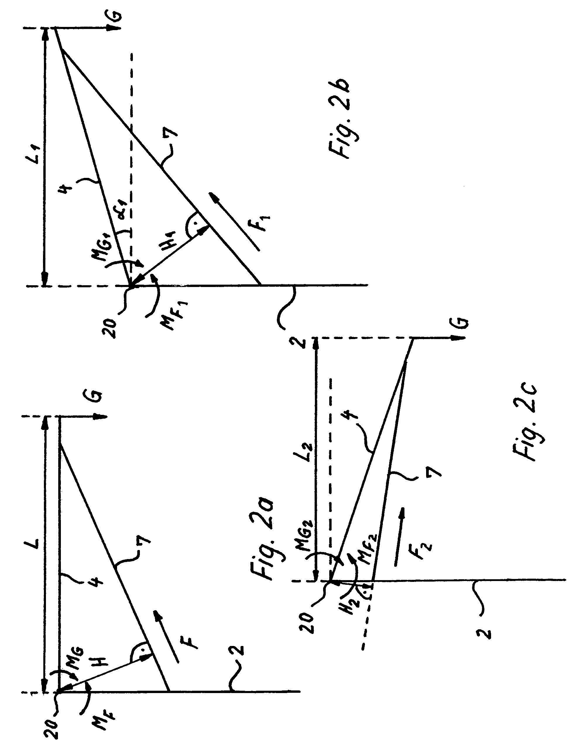
Conventional gas-spring-braced stands have the disadvantage that because of the so-called “cosine function” of the load lever effect of the microscope along its vertical movement arc, the bracing effect that is present differs as a function of the angular position of the horizontal support with respect to the vertical support.
It has been found in practical use, however, that this known configuration is disadvantageous in that the proximal end of the piston rod does not move continuously in the arc-shaped elongated guidance hole but instead, when used, jumps from one extreme position to the other in the manner of a toggle lever; for a user, this requires an additional movement across the jumping point in order to achieve readjustment of the support conditions in the arc-shaped elongated guidance hole.
An inequality between these two torques is expressed, for the operator, in two disadvantageous ways: either the microscope moves by itself into a different location, or for one range the operator requires one specific pivoting force in order to move the microscope, but then suddenly a different force.
That range can be in the middle of the overall pivot angle range, or at the margins; but with the known stand approaches using energy storage elements a compromise is always arrived at between the optimum and disadvantageous range.
These actions, however, place limits on the stand design.
This result is unexpected, since one would necessarily have assumed that a displacement of the optimum articulation point would result in an even greater difference between the torques.
The magnitude of this improvement is also unexpectedly high.

Method used


Image

  • Stand, in particular for surgical microscopes, having an energy storage element
  • Stand, in particular for surgical microscopes, having an energy storage element
  • Stand, in particular for surgical microscopes, having an energy storage element

Examples


Embodiment Construction

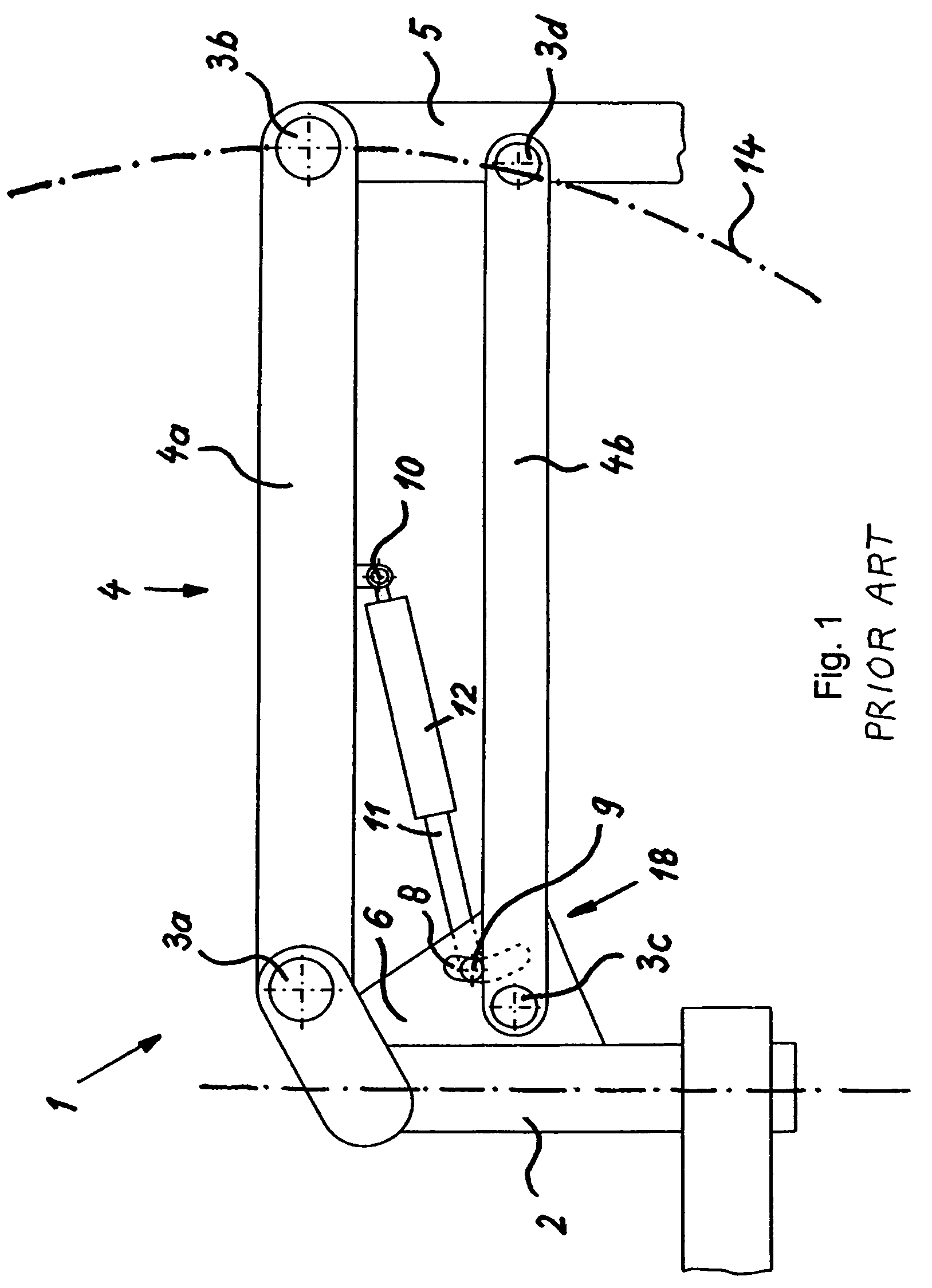
[0025]FIG. 1 schematically depicts a stand arrangement 1 according to the existing art. Stand 1 comprises a vertical support 2 and a horizontal support 4 that is implemented as a parallelogram support having an upper horizontal support arm 4a and a lower horizontal support arm 4b. A gas spring is arranged, as a supporting energy storage element 7, at a distal articulation point 10 on upper horizontal support arm 4a of horizontal support 4 and at a proximal articulation point 9 in a plate 6. Stand 1 has, as a means for positively influencing hysteresis properties, a displacement apparatus 18 that does not act linearly but instead permits, by way of an arc-shaped elongated guide hole 8, a radial displacement of articulation point 9.

[0026]Gas spring 7 is arranged with a cylinder 12 at distal articulation point 10 and with a piston rod 11 at proximal articulation point 9. This stand arrangement furthermore comprises joints 3a-d and a microscope carrier 5. Horizontal support 4 pivots abo...


PUM


Abstract

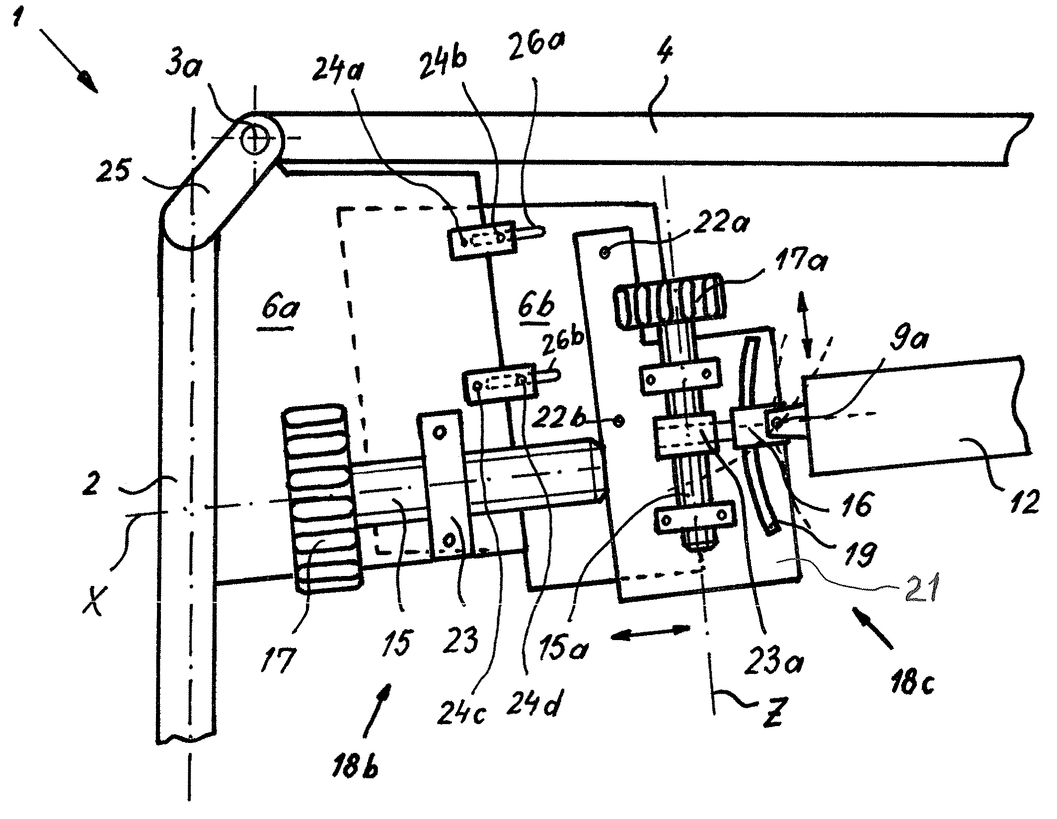
The invention concerns a stand arrangement having an energy storage element (7) and a displacement apparatus (18b) for rotating and / or shifting the proximal articulation point (9a) of the energy storage element (7), and an optimized balancing procedure.

Description

CROSS REFERENCE TO RELATED APPLICATIONS[0001]This application claims priority of the German patent application 10 2004 017 970.0 filed Apr. 12, 2004, which is incorporated by reference herein.FIELD OF THE INVENTION[0002]The invention concerns a stand, in particular a stand for a surgical microscope, having one or more energy storage elements. “Energy storage elements” are understood in general to be elements that are suitable for absorbing energy or force and delivering it again, or converting it into a different form of energy, in defined fashion. Relevant in this context are springs of mechanical, pneumatic, or hydraulic type or a combination of such types, or shock absorbers. Gas springs are primarily used in stand construction, in particular for surgical microscopes, but springs of the other aforementioned types are also implemented.BACKGROUND OF THE INVENTION[0003]In order to achieve a maximally space-saving stand configuration, stands having energy storage elements dispense wi...

Claims


Application Information

Patent Timeline
Patent Type & Authority Patents(United States)
IPC IPC(8): A47F5/00F16M11/04F16M11/06A61B19/00F16M11/18G02B7/00G02B21/00
CPCF16M11/04F16M11/2064G02B7/001F16M2200/044
Inventor METELSKI, ANDRZEJ
Owner LEICA INSTR SINGAPORE PTE
Learn More