Method for coding video pictures by determining a sub-target value for the number of bits per sub-series of coefficients

a video picture and sub-target value technology, applied in the field of video picture coding and decoding methods, can solve the problems of inability to obtain fixed bitrate per picture, inability to achieve fixed bitrate satisfactorily per picture, and inability to achieve fixed bitrate, etc., to achieve small margin and small variation of step size within a picture

Inactive Publication Date: 2007-08-14
U S PHILIPS CORP
View PDF9 Cites 2 Cited by
  • Summary
  • Abstract
  • Description
  • Claims
  • Application Information

AI Technical Summary

Benefits of technology

[0008]It is thereby achieved that the control means control the step size per sub-series, as if they were smaller picture blocks. The actual picture block dimensions are, however, unmodified and may be optimally adapted to the desired transform. The number of sub-series per picture is N times the number of picture blocks and can be freely chosen. The value of N can be chosen to be such that a desired bitrate per picture can be obtained within a very small margin. Moreover, it is achieved that the variation of the step size within a picture is very small. Notably for medical picture sequences, this is an extremely important aspect because a large variation leads to an inhomogeneous picture quality.

Problems solved by technology

However, the X-ray picture characteristics are different from conventional video pictures.
A problem of the known device is that with its step size control a fixed bitrate cannot be satisfactorily obtained per picture if the number of blocks is too small.
The average bitrate is constant over a large number of pictures, but the bitrate may fluctuate to an unwanted large extent per picture.

Method used


Image

  • Method for coding video pictures by determining a sub-target value for the number of bits per sub-series of coefficients
  • Method for coding video pictures by determining a sub-target value for the number of bits per sub-series of coefficients
  • Method for coding video pictures by determining a sub-target value for the number of bits per sub-series of coefficients

Examples


first embodiment

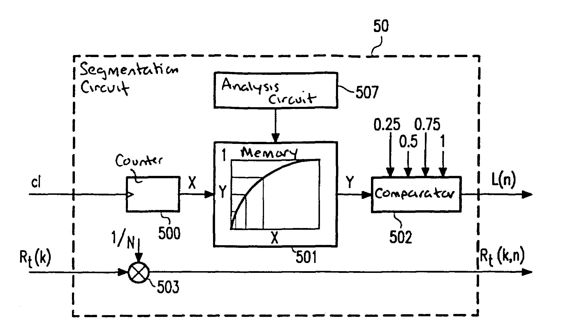
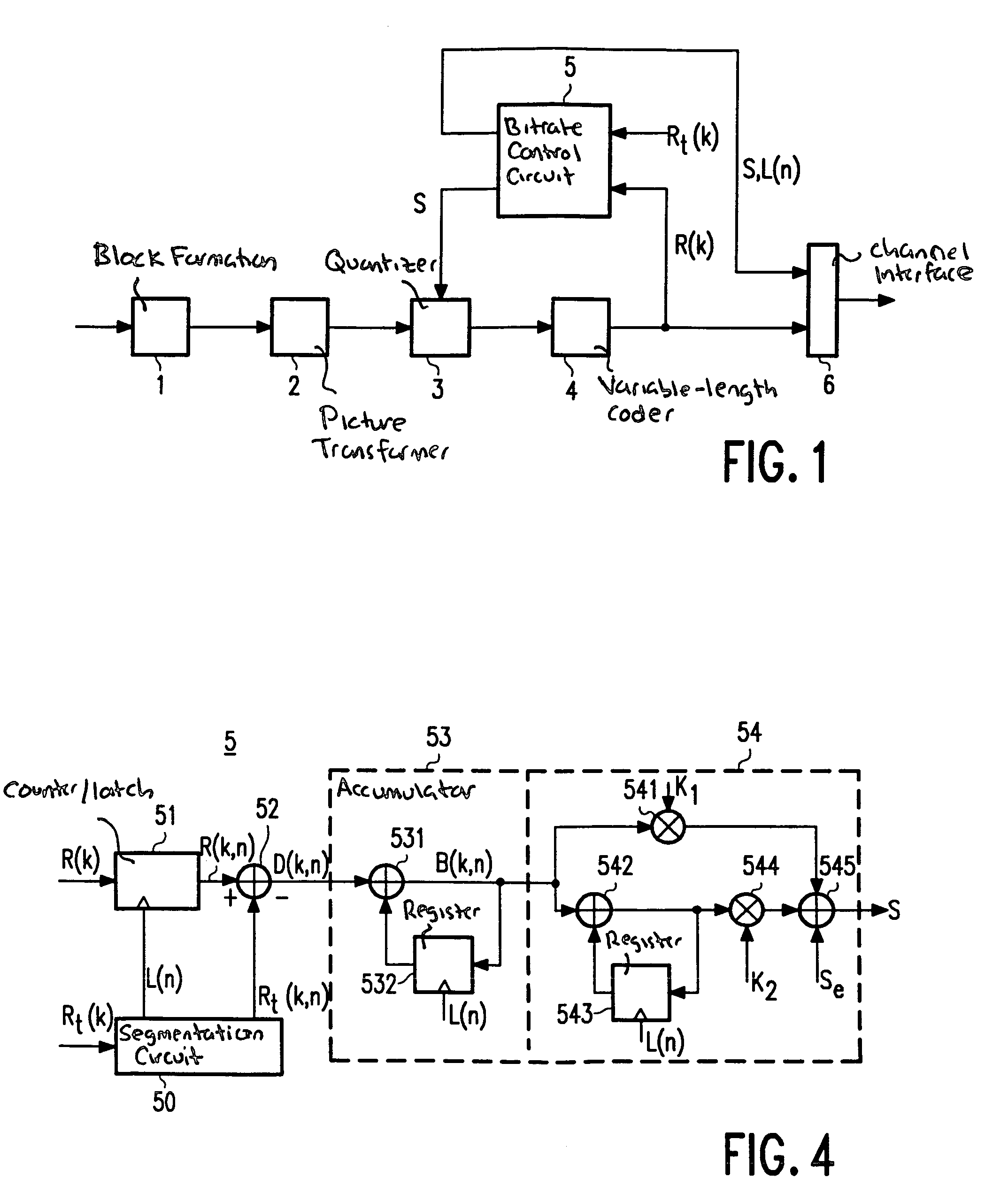
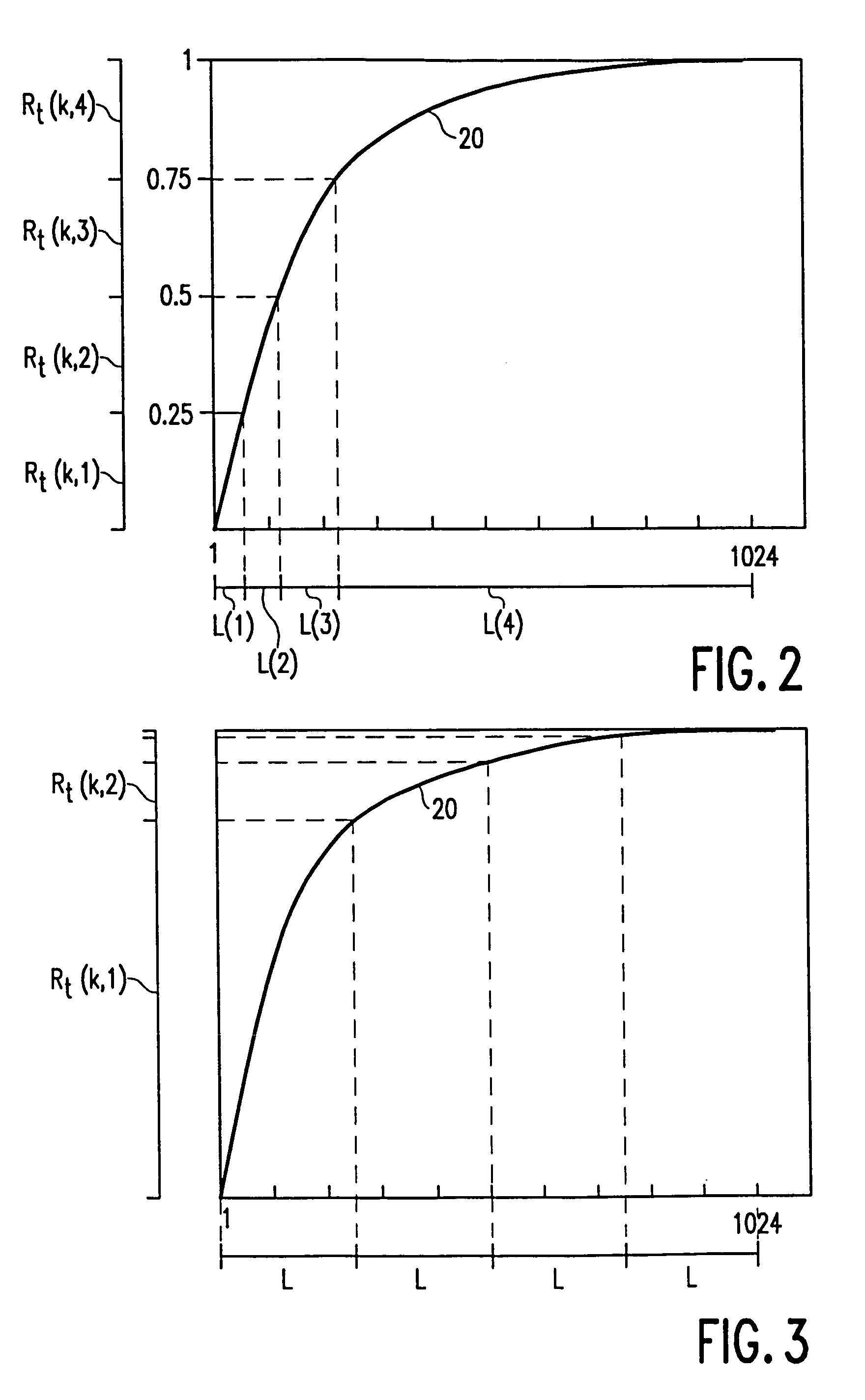
[0026]FIG. 5 shows the segmentation circuit 50. This embodiment is adapted to divide a series of coefficients into segments in accordance with FIG. 2. The segmentation circuit receives a clock signal c1 for each coefficient applied by picture transformer 2 to quantizer 3 (see FIG. 1). The clock signal is applied to a coefficient counter 500 which counts down the number of coefficients (1 . . . 1024) per picture block. The count of this counter is applied to a memory 501 in which an estimation of the cumulative distribution of the bit cost per picture block (see FIG. 2) is stored. The applied count represents a value of said cumulative distribution on the x axis. In response to the applied value x, memory 501 supplies the corresponding y value to a comparator 502. As soon as the y value has predetermined values (0.25, 0.50, 0.75 and 1 for N=4), said comparator supplies the latch signal L(n). Moreover, the segmentation circuit receives the target value Rt(k) for the number of bits per...

second embodiment

[0027]FIG. 6 shows the segmentation circuit 50. This embodiment is adapted to divide a series of coefficients into segments in accordance with FIG. 3. The segmentation circuit comprises the same coefficient counter 500 and memory 501 as the previous embodiment. The clock signal c1 is now also applied to a divider 504 which generates the latch signal L(n) always after 256 coefficients (N times per picture block). The y value supplied by memory 501 is applied by means of the latch signal to a computing circuit 505. With reference to the actual and the previous y value, this computing circuit determines the fraction F(n) of the number of bits Rt(k) which can be spent on coding of the actual segment. Said fraction F(n) is multiplied in a multiplier 506 by the target value Rt(k) so as to obtain the sub-target value Rt(k,n).

[0028]The memory 501 in FIGS. 5 and 6 may be a ROM in which an estimation once determined for the cumulative distribution of the bit cost per picture block is stored. ...


PUM


Abstract

The bitrate control of known video encoders is based on a control of the quantization step size per picture block. In transform coding of relatively large picture blocks, the video picture comprises a too small number of picture blocks to obtain a desired number of bits per picture. In conformity with the invention, the target value for the number of bits per picture block is divided into N sub-targets (Rt(k,n)). The series of coefficients of a picture block is divided into N segments (L(n)) with reference to an estimation for the cumulative distribution 20 of the bit cost per picture block. The quantization step size is subsequently adapted per segment to the corresponding sub-target. Since the number of segments is N times larger than the number of picture blocks, an accurate bitrate control is possible. If desired, the estimation for the cumulative distribution is adapted from picture to picture.

Description

FIELD OF THE INVENTION[0001]The invention relates to a device and a method for coding and decoding video pictures.BACKGROUND OF THE INVENTION[0002]A known device for coding video pictures is described in “Hardware Implementation of the Framestore and Data Rate Control for a Digital HDTV-VCR” presented at the HDTV Symposium in Japan, November 1992. The known device comprises a picture transformer for obtaining a series of coefficients which is representative of a picture block, a quantizer for quantizing the series of coefficients with a step size, and an encoder for coding the series of coefficients. Moreover, the known device comprises control means for controlling the step size in conformity with a target value for the number of bits per series of coefficients.[0003]The device supplies a bit stream with a variable bitrate. To obtain a fixed bitrate per picture (or group of pictures), the known device comprises a buffer in which the bit stream is written at a variable bitrate and i...

Claims


Application Information

Patent Timeline
Patent Type & Authority Patents(United States)
IPC IPC(8): H04N7/12H04N7/30
CPCH04N19/176H04N19/172H04N19/149H04N19/18H04N19/60H04N19/126H04N19/115H04N19/146
Inventor BREEUWER, MARCELKLEIN GUNNEWIEK, REINIER B. M.
Owner U S PHILIPS CORP
Why Eureka
Try Eureka