Synchronized data processing of broadcast streams between receivers, including synchronized data processing between a receiver that is in the process of processing a stream and a receiver that wants to join the stream

a technology of synchronized data and broadcast streams, applied in the field of synchronizing data processing, can solve the problems of serious degrading user experience, inability to adjust the transmission of media streams, and further problems, and achieve the effect of reducing the maximum synchronization delay, reducing the theoretical delay, and increasing the

Active Publication Date: 2017-10-24
KONINK KPN NV
View PDF20 Cites 0 Cited by
  • Summary
  • Abstract
  • Description
  • Claims
  • Application Information

AI Technical Summary

Benefits of technology

[0023]Thus a minimum effect of the invention as claimed would be achieved if this minimum theoretical delay could be shortened. This minimum effect could be achieved if synchronization could be already accomplished with a data unit that is one earlier in the order of processing by the first receiver. The one data unit that is earlier in processing would in this scenario correspond to the last one transmitted in the broadcast to the first receiver at the moment the second broadcast stream is requested (by the second receiver). Because the corresponding data unit in the second broadcast stream has also just been sent (assuming both broadcast streams relate to the same broadcast), it can no longer be received as part of the second broadcast stream by the second receiver.
[0024]Therefore, according to the invention, a data unit corresponding to this ‘last transmitted’ data unit in the second broadcast stream is selected from a location where this data unit is stored. This smart selection of a data unit for transmission separately from the second broadcast stream, enables ‘earlier’ synchronization than what is possible had only the second broadcast stream be provided to the second receiver.
[0025]For making this smart selection in a ‘de minimis’ scenario, no further information about the processing point of the first receiver is needed. However the invention as claimed also teaches a boundary where the smart selection of data units could reach its theoretical maximum effect. This boundary is best described as the scenario wherein a data unit is selected that has a corresponding data unit (one with the same position of the common timeline) that has not yet been (but is the next-in line to be) processed (played-out) by the first receiver. This theoretical boundary assumes that such selected data unit could be transmitted fast enough so that it is ready for processing by the second receiver in synchronization with the processing of the corresponding data unit at the first receiver.
[0026]This theoretical boundary thus defines the data unit to be selected for achieving a maximum decrease in synchronization delay.
[0027]In summary the invention is based on selecting from a range of data units wherein the boundaries are associated with the theoretical minimum and maximum effects to be achieved. It is clear to the skilled person that the more the selection of data units according to the invention is aimed at achieving a greater effect, additional measures according to aspects of the invention may be needed. This is because the room for margin becomes smaller when earlier data units (selected data units corresponding to data units being broadcast earlier in time) are selected. E.g. there is less time left for getting these data units transmitted to the second receiver and ready for processing by the second receiver in sync with the processing of corresponding data units by the first receiver. The additional measures become readily apparent when reading the specification. These may for example including the use of processing point information of the first receiver in the selection, which better defines how much margin is available in the selection. These measures may also include using expected or measured play-out delays at the first and second receiver, to be able to make more precise estimates of the margin. And furthermore fast channel change methods (bursting) may be used for transmitting the selected data units at enhanced speed (e.g. a speed greater than the first or second broadcast stream) to the second receiver.
[0028]The relation between data units of the first and second stream may be used to select data units corresponding to data units of the second stream that are stored in a memory. The selected data units may be transmitted (in a burst) to the second receiver which may use these transmitted selected (burst) data units to reduce the time that is needed for the second receiver to join a stream in synchronization with one or more further receivers.

Problems solved by technology

As (live) content is often distributed on the basis of multicast or broadcast, the source is by definition not able to adjust the transmission of the media streams to the different receivers.
Hence, the process of joining an IDMS synchronized session may seriously degrade the user experience.
In other applications, further problems may occur.
This means that crucial information could be missed, even if the user himself has a high capacity and low-latency network connection with the interactive classroom.
Montagud does not address the problem of achieving a synchronized state between a receiver or a group of receivers that is in the process of playing a stream and a receiver that wants to join the streaming session in sync.
Furthermore, the solution of Montagud is not suitable for applications such as a live streaming application wherein the system should be able to provide fast or even seamless realization of a synchronized state between a joining receiver and a receiver or a group of receivers that is already playing the media.

Method used


Image

  • Synchronized data processing of broadcast streams between receivers, including synchronized data processing between a receiver that is in the process of processing a stream and a receiver that wants to join the stream
  • Synchronized data processing of broadcast streams between receivers, including synchronized data processing between a receiver that is in the process of processing a stream and a receiver that wants to join the stream
  • Synchronized data processing of broadcast streams between receivers, including synchronized data processing between a receiver that is in the process of processing a stream and a receiver that wants to join the stream

Examples


Embodiment Construction

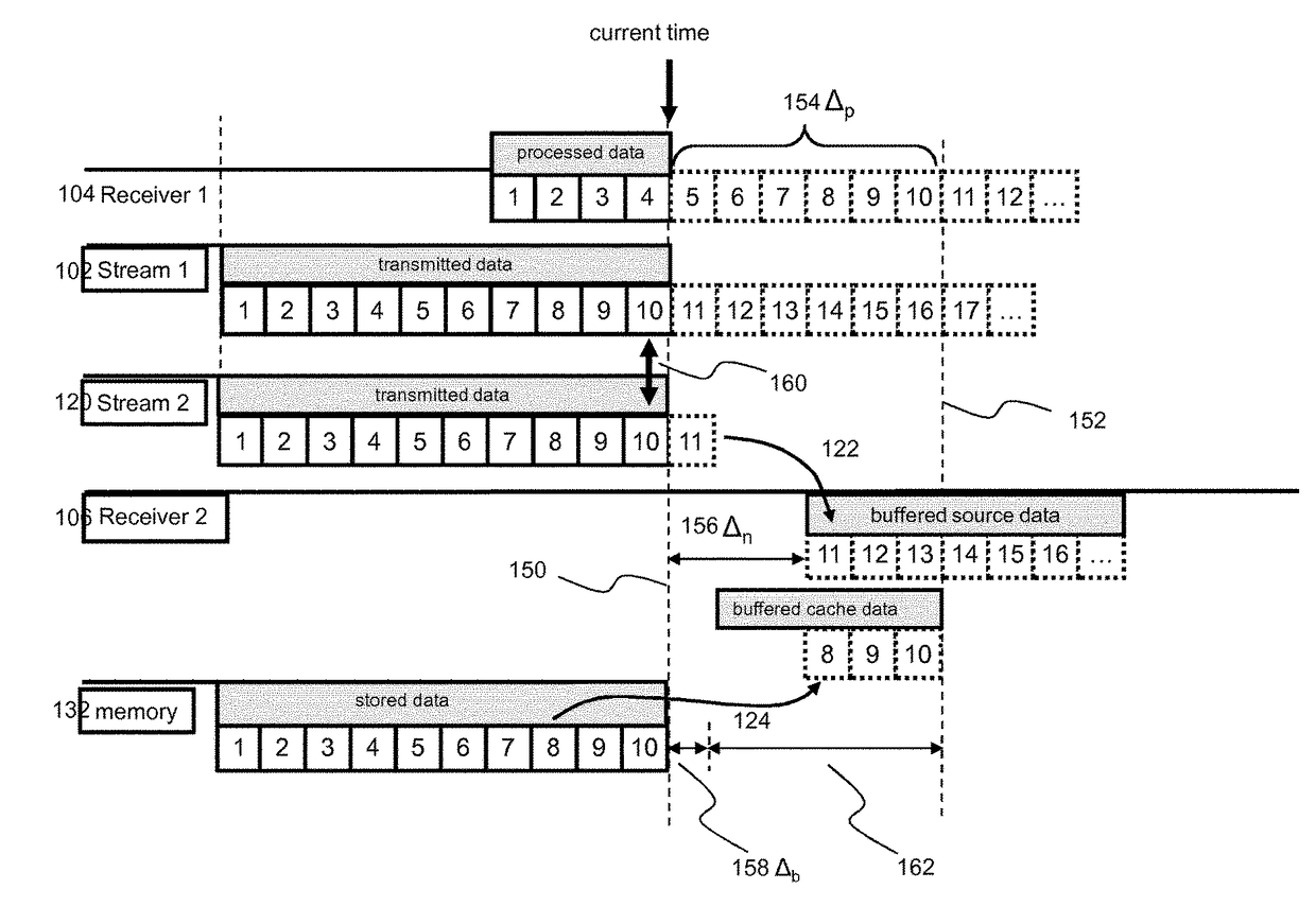
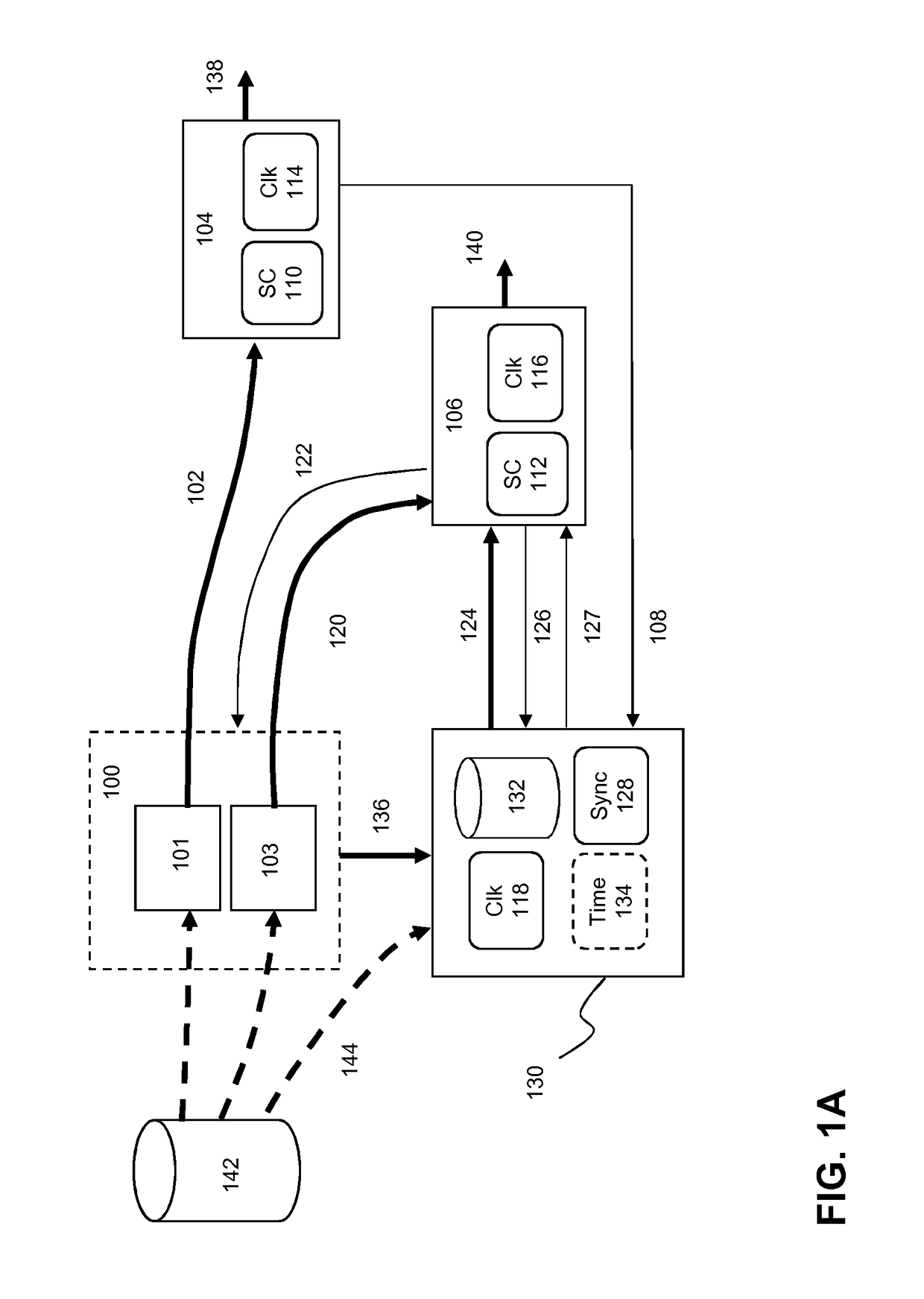
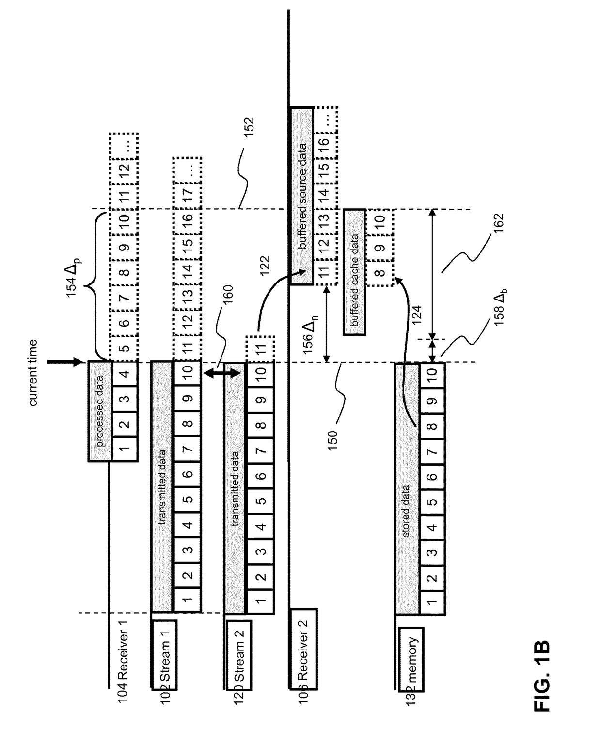
[0064]For the purpose of this invention the term receiver refers to a computer arranged for receiving a digitalized data stream. Examples of a receiver are home gateways, mobile terminals such as smartphones, television sets, tablets, laptops, set top boxes, wearables (e.g. Google Glass) and so on. The term client device generally refers to a module comprising the functionality for executing one or more parts of the method according to one or more embodiments of the invention. The module is suitable for use in a receiver (system). As such, and when independently claimed, the client device relates to a hardware component for use in a receiver, or to the receiver itself. Examples of such a hardware component may be a System on a Chip (SoC), a Radio Card, a Printed Circuit Board, or an Integrated Circuit. Likewise the functions and capabilities of the client device may also be implemented on a receiver as software or a combination of software and hardware components. The terms client a...


PUM


Abstract

In an embodiment, synchronization of data processing by a first and second receiver is enabled by the first receiver processing data units of a first broadcast stream, with a play-out delay Δtp defining a time interval between transmission of a data unit to the first receiver and the processing of the data unit by the first receiver. Transmission of data units of a second broadcast stream is initiated to the second receiver, a common timeline correlating one or more data unit in the first stream with one or more corresponding data unit in the second stream. One or more data units is selected from stored data units corresponding to the second stream. At least part of the selected data units have corresponding data units of the first stream that have been transmitted to the first receiver but that have not been processed by the first receiver due to the play-out delay.

Description

[0001]This application is the U.S. National Stage of International Application No. PCT / EP2014 / 064602, filed Jul. 8, 2014, which designates the U.S., published in English, and claims priority under 35 U.S.C. §§119 or 365(c) to European Application No. 13175671.0, filed Jul. 9, 2013.FIELD OF THE INVENTION[0002]The invention relates to synchronizing data processing, and, in particular, though not exclusively, to a method for enabling synchronized data processing between receivers, a client device and a synchronization server for enabling such synchronization and a computer program product for using such method.BACKGROUND OF THE INVENTION[0003]With the growing popularity of Internet video and Internet TV, there is an increasing need for streaming solutions that allow a shared synchronized user experience for a group of users. Such synchronized streaming services may be provided to a plurality of users, which are located at different locations. The process for achieving synchronized play...

Claims


Application Information

Patent Timeline
Patent Type & Authority Patents(United States)
IPC IPC(8): H04N21/242H04N21/43H04N21/426
CPCH04N21/242H04N21/4302H04N21/43H04N21/4263
Inventor BANGMA, MENNOVAN BRANDENBURG, RAY
Owner KONINK KPN NV
Why Eureka
Try Eureka