A flange seat, its manufacturing method, and hoisting machinery

A manufacturing method and flange seat technology are applied in the fields of hoisting machinery, flange seats and manufacturing, which can solve the problems of high labor intensity, low welding efficiency, large welding stress, etc., so as to reduce labor intensity and improve production efficiency. , The effect of reliable welding quality

Active Publication Date: 2021-09-21
湖南中铁五新重工有限公司
View PDF0 Cites 0 Cited by
  • Summary
  • Abstract
  • Description
  • Claims
  • Application Information

AI Technical Summary

Problems solved by technology

[0005] 1. The ear plate and the bottom plate have large dimensions and heavy weight. It is inconvenient to install the positioning point after the ear plate is grooved, and multiple people are needed to assist;
[0006] 2. The thickness of the ear plate is thick, the volume of the welding pool is large after the groove is opened, the welding heat energy is concentrated, and the welding efficiency is low (currently it takes more than 3 days to make a flange seat), and the labor intensity of the workers is high;
[0007] 3. The welding stress is large and the deformation is large, which is difficult to eliminate and uncontrollable;
[0009] 5. Due to the large welding deformation, more machining allowances need to be reserved for the ear plate and the bottom plate when preparing and unloading materials, resulting in a large amount of subsequent machining, affecting production efficiency, and wasting materials;
[0010] 6. Low production efficiency, high manufacturing cost and unstable quality

Method used


Image

  • A flange seat, its manufacturing method, and hoisting machinery
  • A flange seat, its manufacturing method, and hoisting machinery
  • A flange seat, its manufacturing method, and hoisting machinery

Examples


Embodiment 1

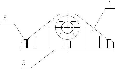
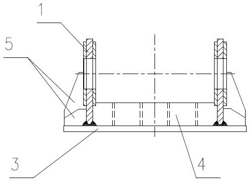
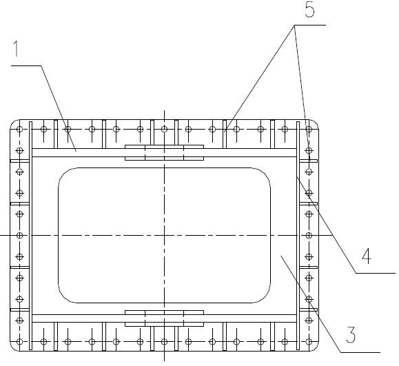
[0066] Such as Figure 4-Figure 7 As shown, the flange seat of this embodiment includes a bottom plate 3 , two lug plate assemblies, two sealing plates 4 and multiple rib plates 5 .

[0067] Let one of the length direction and the width direction of the bottom plate 3 be the X direction, and the other direction be the Y direction, and two ear plate assemblies are arranged on the bottom plate 3 and arranged at intervals along the X direction, as Figure 11 As shown, the bottom of the ear plate assembly is divided into N notch parts and N+1 socket parts 14 along its length direction, N≥1, and the bottom surface of the notch part is depressed upwards to form a groove that runs through the two walls of the ear plate in the thickness direction Mouth 11, such as Figure 12 As shown, the bottom plate 3 is provided with a through groove 31 that cooperates with the socket portion 14 of the ear plate assembly, and the socket portion 14 is clamped in the corresponding through groove 31 ...

Embodiment 2

[0074] In this embodiment, auxiliary tooling and auxiliary welding machines are used to complete the welding of the flange seat in embodiment 1. Among them, the auxiliary tooling includes a rotary tooling that makes each weld seam of the flange seat in a flat welding position, a clamp 7 for fixing the flange seat, and a limit structure 8 for preventing the deformation of the lug plate 1, and for preventing the deformation of the lug plate 1. The adornment shaft 9 that controls the coaxiality of the two hinge shaft holes 12 on the two ear plates 1. Among them, the rotary tooling includes a driving device 6, a working platform 61 connected to the driving device 6, and a clamp 7 connected to the working platform 61 for horizontal rotation, and the driving device 6 can drive the working platform 61 to turn vertically. The welded flange seat can drive the flange seat to rotate horizontally relative to the working platform 61 .

[0075] Such as Figure 13-16 Shown, the manufacturi...


PUM


Abstract

The invention discloses a flange seat, a manufacturing method thereof, and a lifting machine. The flange seat includes a bottom plate and two ear plate assemblies. The two ear plate assemblies are arranged on the bottom plate and arranged at intervals along the X direction. The bottom of the ear plate assembly Along its length direction, it is divided into N notch parts and N+1 socket parts, N≥1. The bottom surface of the notch part is depressed upwards to form a notch that runs through the two wall surfaces in the thickness direction of the lug plate. A through groove that cooperates with the socket part of the lug plate assembly, and the socket part is clamped in the corresponding through groove and connected with the bottom plate by full welding. Therefore, by processing the slotted holes and notches embedded in each other on the bottom plate and the lug plate, the positioning is formed during spot assembly, so that most of the force on the flange seat is transmitted by the contact part of the bottom plate and the lug plate, and the butt welding Seam requirements are relatively reduced, welding deformation and labor intensity are reduced.

Description

technical field [0001] The invention relates to the technical field of lifting equipment, in particular to a flange seat and a manufacturing method, as well as a lifting machine with the flange seat. Background technique [0002] At present, the metal structure assembly of gantry cranes, gantry cranes, shoreside container cranes, bulk cargo handling machinery and other equipment are connected to the cart operating mechanism by using flange seats as transition pieces, and the bottom plate of the flange seats is connected to the metal structure. In the structural part, the hinge shaft hole of the lug plate is connected to the traveling mechanism of the cart. The flange seat has a compact structure and an asymmetric structure. It is subjected to a large force during work and requires high welding requirements. The plate thickness of the main parts is large, the welding deformation is large, the production efficiency is low, and the labor intensity of the workers is high. [00...

Claims


Application Information

Patent Timeline
Patent Type & Authority Patents(China)
IPC IPC(8): F16C11/04B66C13/00B23K31/02B23K37/04B23K37/047
CPCB23K31/02B23K37/0443B23K37/047B66C13/00F16C11/04F16C2226/36
Inventor 任军辉张维友张桂袁光金罗红亮
Owner 湖南中铁五新重工有限公司
Why Eureka
Try Eureka