Air cleaner

a technology for cleaning devices and air, applied in the direction of filtration separation, human health protection, separation processes, etc., can solve the problems of replacing filters, needing a powerful fan, and consuming more power,

Active Publication Date: 2007-08-21
HELEN OF TROY LTD
View PDF20 Cites 49 Cited by
  • Summary
  • Abstract
  • Description
  • Claims
  • Application Information

AI Technical Summary

Benefits of technology

[0009]In another aspect of the present invention, an exemplary embodiment of an arrangement for removably inserting a filter element into an air cleaning device is provided. The exemplary arrangement also removably provides electrical contact between the filter element and the air cleaning device.

Problems solved by technology

FACs suffer from several drawbacks including a marked drop-off of air flow as the filter becomes increasingly blocked with collected particles; the need for a powerful fan due to the significant pressure drop across the filter (powerful fans also tend to generate more noise and consume more power than less powerful fans); and the need to periodically replace the filter.
Even after the power supply has been switched off, there is the danger of shock from electrical charges stored on the plates.
Furthermore, electrical breakdown and leakage between the metal plates will cause a loss of efficiency and generate ozone.
Increasing the spacing between the plates will reduce electrical breakdown in the air but will also reduce efficiency.

Method used


Image

  • Air cleaner
  • Air cleaner
  • Air cleaner

Examples


Embodiment Construction

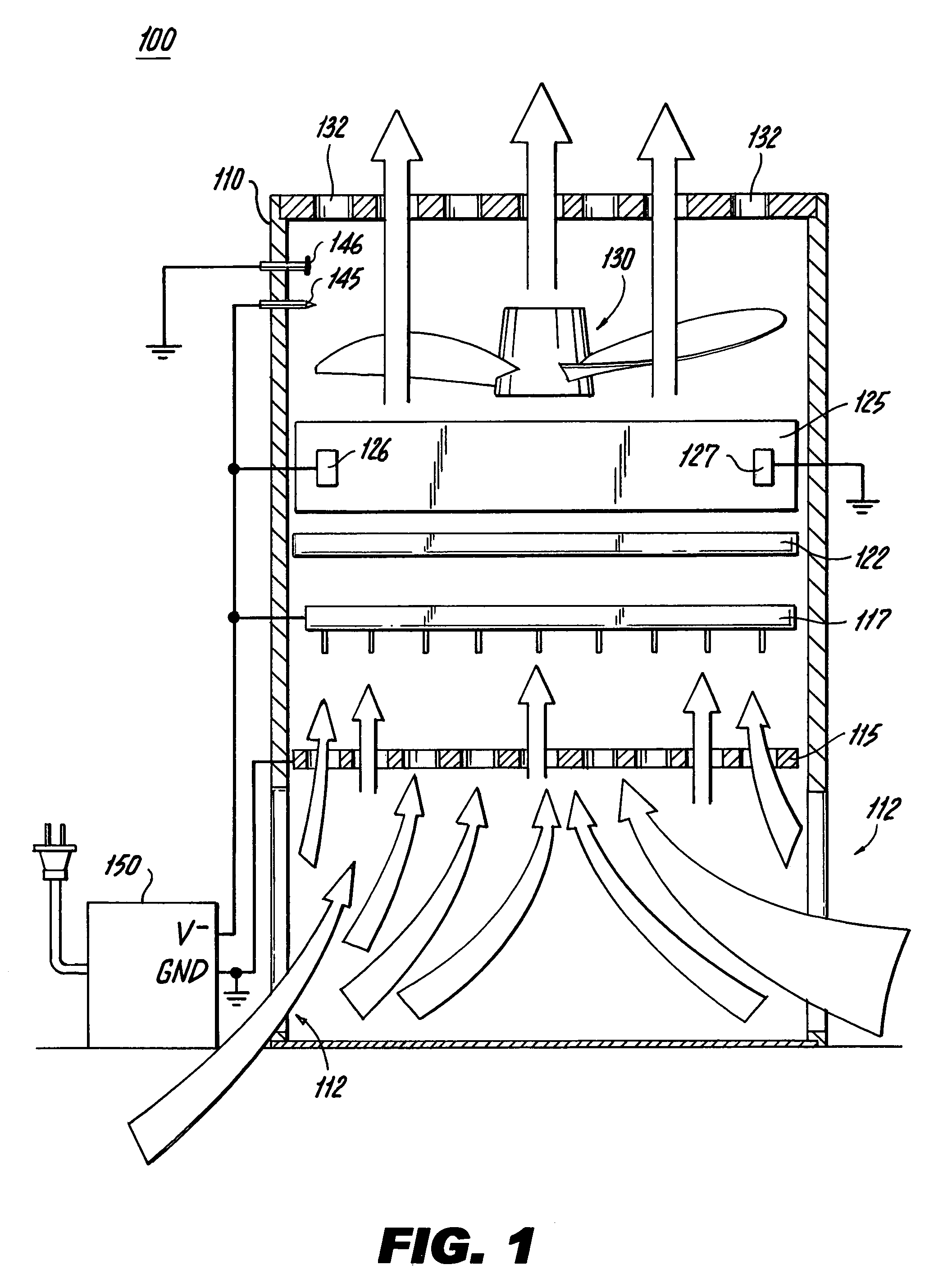
[0018]An exemplary embodiment of an air cleaning device 100 in accordance with the present invention is illustrated schematically in FIG. 1. Arrows indicate the flow of air through the air cleaning device 100. The device 100 comprises a housing 110 having air inlet vents 112 arranged generally along a lower portion of the housing, with the vents 112 preferably extending 360 degrees around the housing.

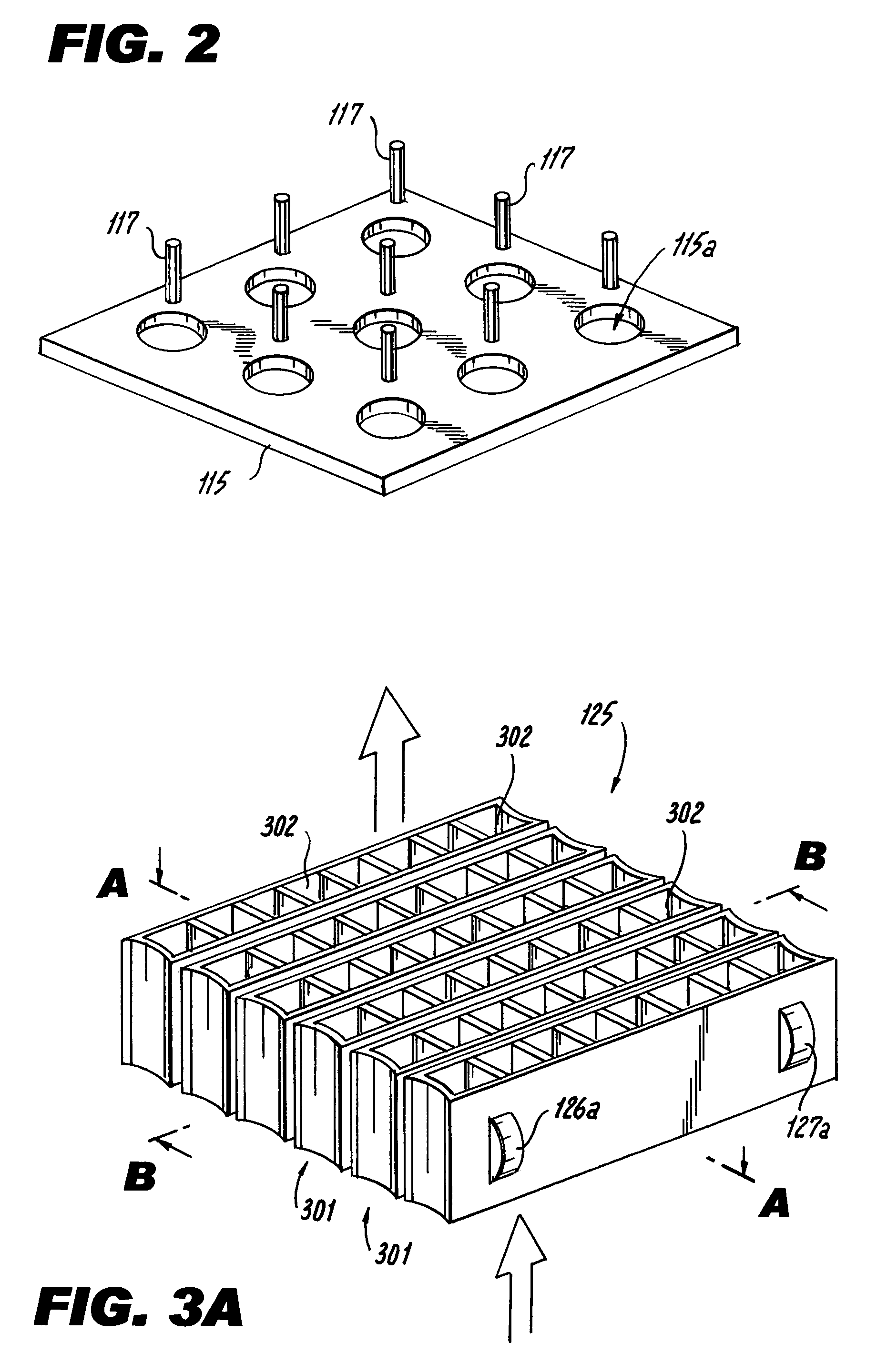
[0019]An ionization plate 115 is arranged within the housing downstream of the inlet vents 112. The ionization plate 115, described more fully below, comprises a plurality of openings allowing air to pass there through. An array of pin electrodes 117 is arranged downstream of the ionization plate.

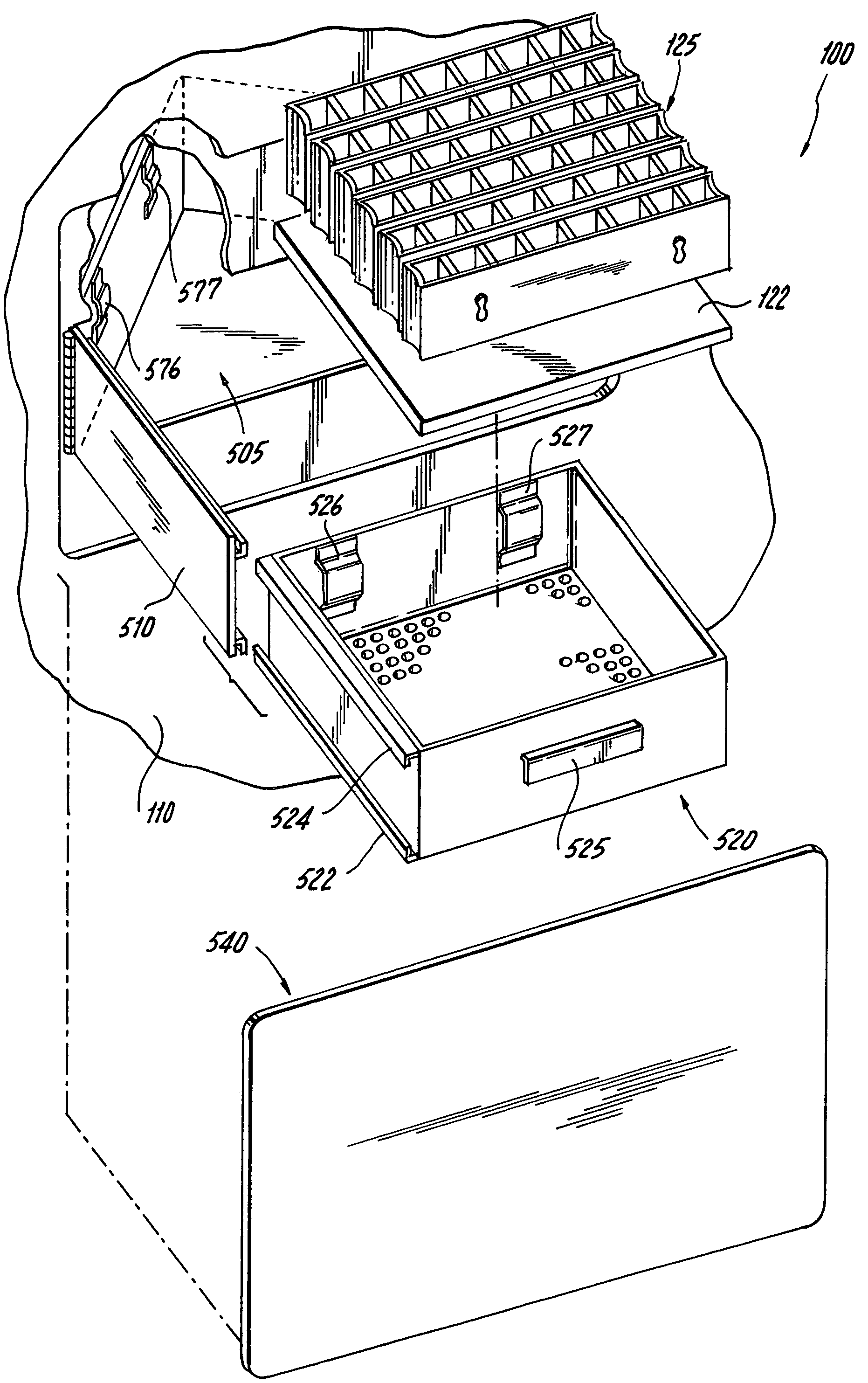
[0020]A pre-filter 122 is arranged downstream of the pin electrodes 117 and a filter 125 is arranged downstream of the pre-filter 122. The filter 125 can be implemented as described in U.S. Pat. No. 6,749,669 (hereinafter the “'669 patent”), entitled AIR CLEANING DEVICE, which is herein incorpo...


PUM

PropertyMeasurementUnit
voltageaaaaaaaaaa
voltageaaaaaaaaaa
electricallyaaaaaaaaaa

Abstract

An improved filter element for use in an electrostatic precipitation air cleaning device, the filter element including rod electrodes arranged through a stack of alternating fluted plastic sheets and plate electrodes. Successive plate electrodes are arranged to make contact with an alternating one or the other of the rod electrodes. The plate and rod electrodes may be composed of high impedance materials such as paper and plastic, respectively. An arrangement for removably inserting a filter element into an air cleaning device is provided. The arrangement also removably provides electrical connectivity between the filter element and the air cleaning device. The filter element can thus be readily removed and re-installed by a user.

Description

FIELD OF THE INVENTION[0001]The present invention relates to air cleaning devices, in particular to particle precipitation devices for removing particles entrained in an air stream.BACKGROUND INFORMATION[0002]Conventional air cleaners, such as filtration air cleaners (FACS) remove particles from the air by trapping the particles in filters. Other air cleaners, such as electrostatic precipitation air cleaners (ESPACs), remove particles from the air by collecting the particles on electrically charged collection surfaces, usually one or more metallic plates coupled to high voltages. Once full of captured particles, the filters or plates may then be disposed of, washed or replaced, thereby necessitating convenient and safe access to the filters or plates.[0003]FACs suffer from several drawbacks including a marked drop-off of air flow as the filter becomes increasingly blocked with collected particles; the need for a powerful fan due to the significant pressure drop across the filter (po...

Claims


Application Information

Patent Timeline
Patent Type & Authority Patents(United States)
IPC IPC(8): B01D46/10B03C3/47
CPCB03C3/09B03C3/41B03C3/51B03C3/74B03C2201/10Y02A50/2351
Inventor COX, PAUL E.GATCHELL, STEPHEN M.BEST, JAMES J.VORDENBERG, STEVENKONTOROVICH, BORISLOZEAU, KEVIN
Owner HELEN OF TROY LTD
Why Eureka
Try Eureka