Communications jack with printed wiring board having paired coupling conductors

a technology of coupling conductors and communication jacks, which is applied in the direction of coupling device details, coupling device connections, printed circuit aspects, etc., can solve the problems of undesirable signals, negative impact on other electrical properties, and each wire in a wire-pair is susceptible to picking up electrical noise, etc., and achieves the effect of increasing the return loss

Active Publication Date: 2007-09-04
COMMSCOPE INC
View PDF80 Cites 40 Cited by
  • Summary
  • Abstract
  • Description
  • Claims
  • Application Information

AI Technical Summary

Benefits of technology

[0010]As a fourth aspect, embodiments of the present invention are directed to a method of increasing return loss in a communications connector, the connector comprising a wiring board and a plurality of conductors mounted thereon, the conductors being electrically connected with electrical terminals that are arranged in pairs. The method comprises the step of coupling sections of two of the conductors electrically connected with a pair of electrical terminals, the sections being immediately adjacent to each other and having identical instantaneous current direction, such that the sections couple and cause a localized increase in inductance.

Problems solved by technology

Each wire in a wire-pair is susceptible to picking up electrical noise from sources such as lightning, automobile spark plugs and radio stations to name but a few.
Of greater concern, however, is the electrical noise that is picked up from nearby wires or pairs of wires that may extend in the same general direction for some distances and not cancel differentially on the victim pair.
In all of the above situations, undesirable signals are present on the electrical conductors that can interfere with the information signal.
Unfortunately, the introduction of compensatory crosstalk can negatively impact other electrical properties.
Achieving acceptable return loss performance, particularly on conductor pairs 1 and 3 (as designated in TIA 568B) of an eight conductor jack, can be especially challenging due to the heavy crosstalk compensation typically required by these two pairs.
Reaching an acceptable compromise between crosstalk compensation and return loss can be exceptionally challenging for plugs that are to meet or exceed Category 6 performance parameters, particularly if data transmission speeds of 10 Gb / s over UTP are desired over a frequency range of 1-500 MHz.

Method used


Image

  • Communications jack with printed wiring board having paired coupling conductors
  • Communications jack with printed wiring board having paired coupling conductors
  • Communications jack with printed wiring board having paired coupling conductors

Examples


example

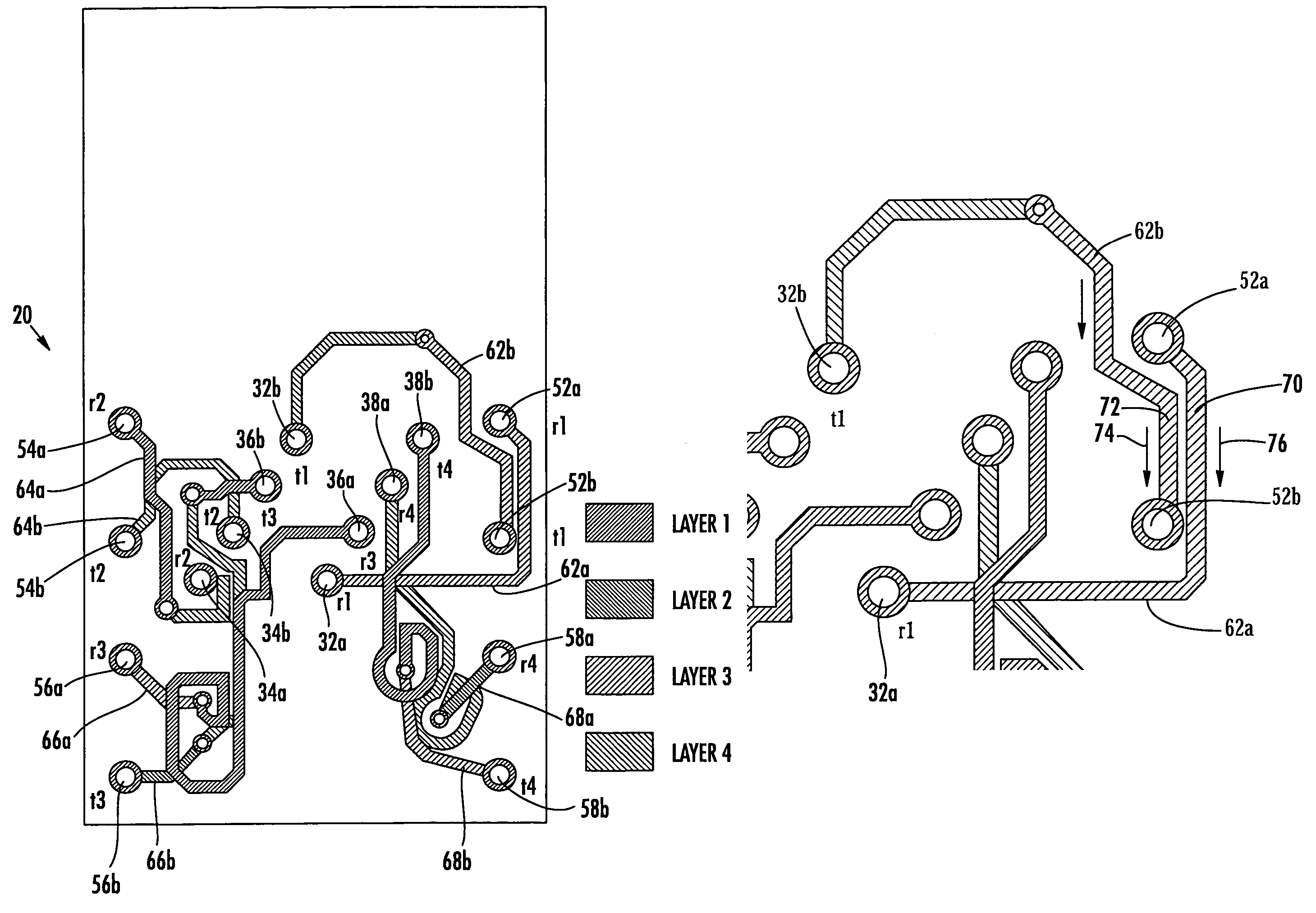
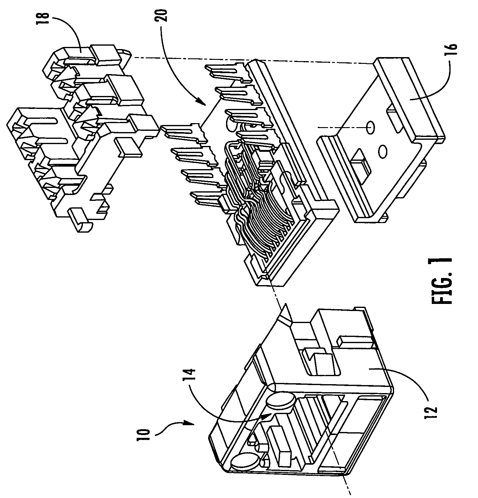
[0033]Communications jacks of the configuration illustrated in FIG. 1 were constructed. In one set of jacks (labeled “experimental jacks” in FIG. 4), the wiring board included conductors of pair 1 that had coupling sections substantially matching those illustrated in FIGS. 2 and 3. In a second set of jacks (labeled “conventional jacks” in FIG. 4), the wiring board included conductors that did not have such coupling sections. The jacks were then tested for return loss on pair 1 under the conditions set forth in TIA / EIA-568-B.2-1 Annex E.

[0034]Results of the testing are shown in FIG. 4. It can be seen that the experimental jack employing the coupling sections exhibited a significant increase in the return loss decibel level (i.e., an improvement) over the conventional jack, at frequencies above about 2.5 MHz.


PUM


Abstract

A communications jack includes: a jack frame having a plug aperture; a plurality of contact wires, the contact wires having free ends that extend into the plug aperture, the free ends of the contact wires being arranged serially in side-by-side relationship; a plurality of electrical terminals, the terminals being arranged in pairs, each pair defining a communication channel; a dielectric mounting substrate, the mounting substrate including a plurality of mounting locations for contact wires and a plurality of mounting locations for the electrical terminals; and a plurality of conductors mounted on the substrate, each of the conductors extending, defining a path, and establishing electrical connection between a contact wire mounting location and an electrical terminal mounting location. First and second of the conductors that are connected to one of the pairs of terminals each include a coupling section, the coupling sections being immediately adjacent to each other and having identical instantaneous current direction such that the sections couple and cause a localized increase in inductance.

Description

RELATED APPLICATIONS[0001]The present application claims priority from U.S. Provisional Patent Application Ser. Nos. 60 / 633,733, filed Dec. 6, 2004, entitled COMMUNICATION PLUG WITH BALANCED WIRING TO MINIMIZE DIFFERENTIAL TO COMMON MODE CROSSTALK, 60 / 636,590, filed Dec. 16, 2004, entitled IMPROVING RETURN LOSS IN CONNECTORS BY CONDUCTOR SELF-COUPLING, 60 / 636,595, filed Dec. 16, 2004, entitled CROSSOVER FOR SIMULTANEOUSLY COMPENSATING DIFFERENTIAL TO DIFFERENTIAL OR DIFFERENTIAL TO COMMON MODE CROSSTALK, and 60 / 648,002, filed Jan. 28, 2005, entitled CONTROLLED MODE CONVERSION PLUG FOR REDUCED ALIEN CROSSTALK, and from U.S. patent application Ser. No. 11 / 051,285, filed Feb. 4, 2005, entitled COMMUNICATION JACK WITH PRINTED WIRING BOARD HAVING SELF-COUPLING CONDUCTOR, the disclosure of each of which is hereby incorporated herein in its entirety.FIELD OF THE INVENTION[0002]The present invention relates generally to communication connectors and more particularly to the improvement of re...

Claims


Application Information

Patent Timeline
Patent Type & Authority Patents(United States)
IPC IPC(8): H01R24/00
CPCH01R13/6658H05K1/0228H01R13/6473H05K2201/10189Y10S439/941H01R13/6467H01R24/64
Inventor HASHIM, AMID I.MOFFITT, BRYANPHARNEY, JULIAN
Owner COMMSCOPE INC
Why Eureka
Try Eureka