
Ultrasonic treatment apparatus

a treatment apparatus and ultrasonic technology, applied in the field of ultrasonic treatment apparatus, can solve the problems of contamination such as blood entering the spacing between the first element and the second element, and the need for ultrasonic treatment apparatus recycling is gradually increasing, and the need for cleaning for a long time is not easy to achiev

Active Publication Date: 2007-09-04
OLYMPUS CORP
View PDF8 Cites 129 Cited by
  • Summary
  • Abstract
  • Description
  • Claims
  • Application Information

AI Technical Summary

Benefits of technology

The present invention relates to an ultrasonic treatment apparatus for performing medical procedures such as cutting, removing, and coagulation of living tissues. The technical effects of the invention include improved cleaning mechanisms for easier recycling and reduced operational costs, as well as a mechanism for tightly contacting the first and second elements with a filling member or a metallic material extended along the probe. The invention also includes a mechanism for pivotably supporting the jaw and a mechanism for easily recycling the apparatus.

Problems solved by technology

In consideration of recent global environmental problems, however, the need for recycling the ultrasonic treatment apparatus is gradually increasing.
Particularly, in the tip action unit that consists of a plurality of elements, contaminants such as blood entering into spacing between the first element and the second element require a very long time to be cleaned.

Method used


Image

  • Ultrasonic treatment apparatus
  • Ultrasonic treatment apparatus
  • Ultrasonic treatment apparatus

Examples


first embodiment

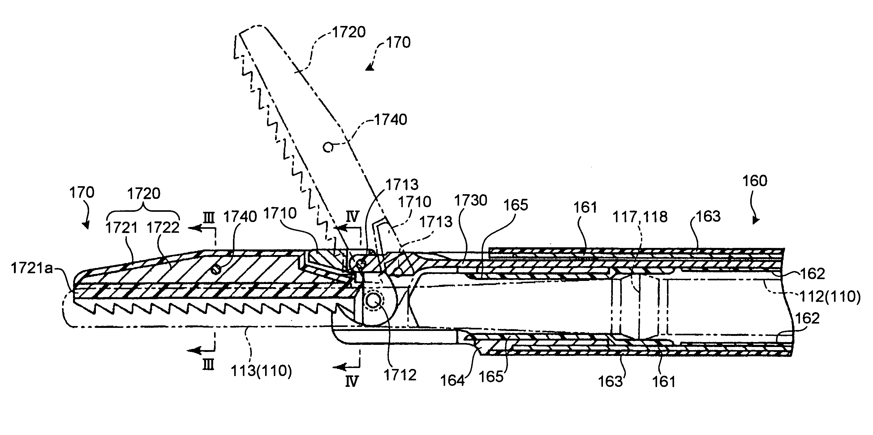
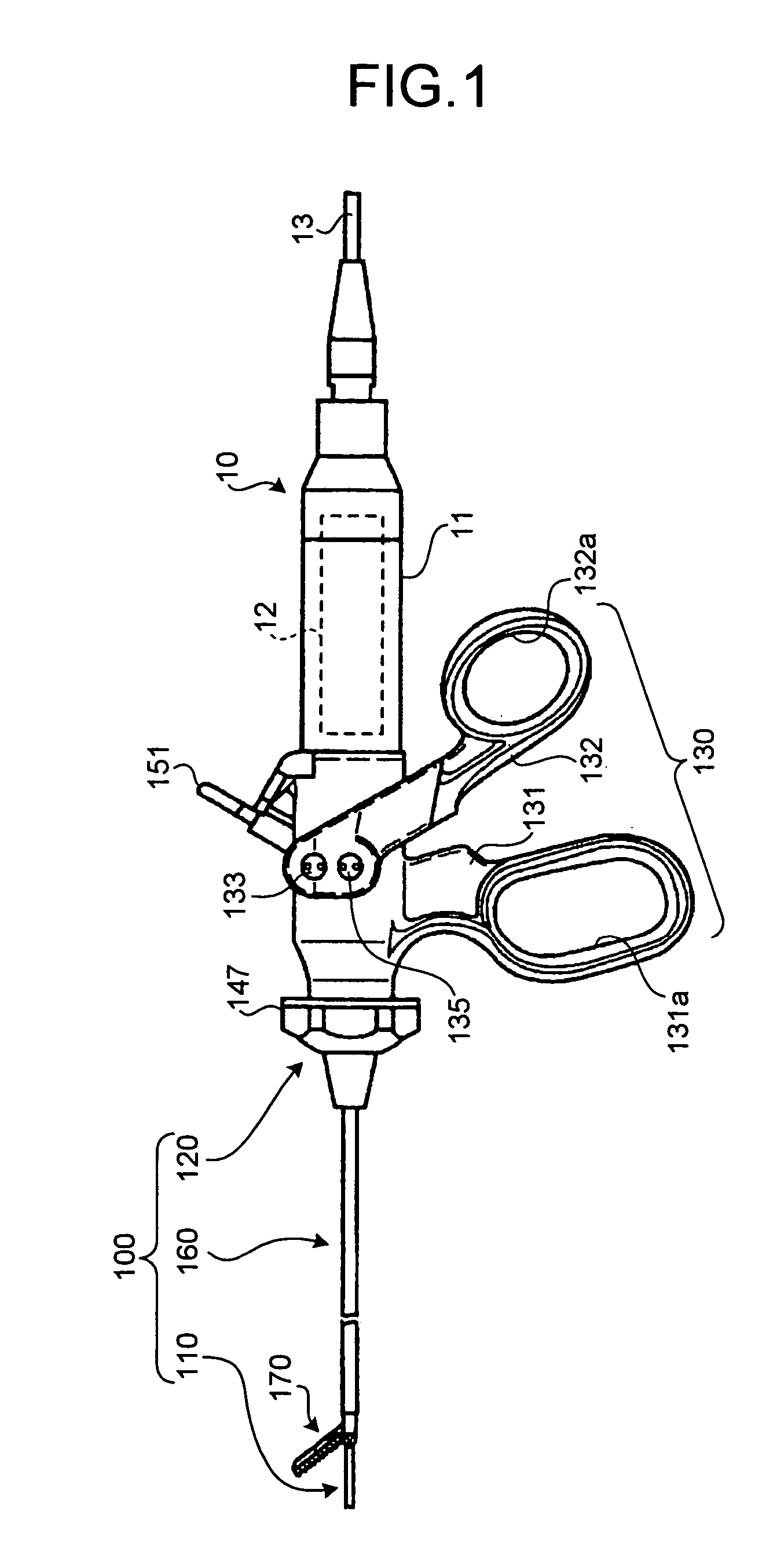
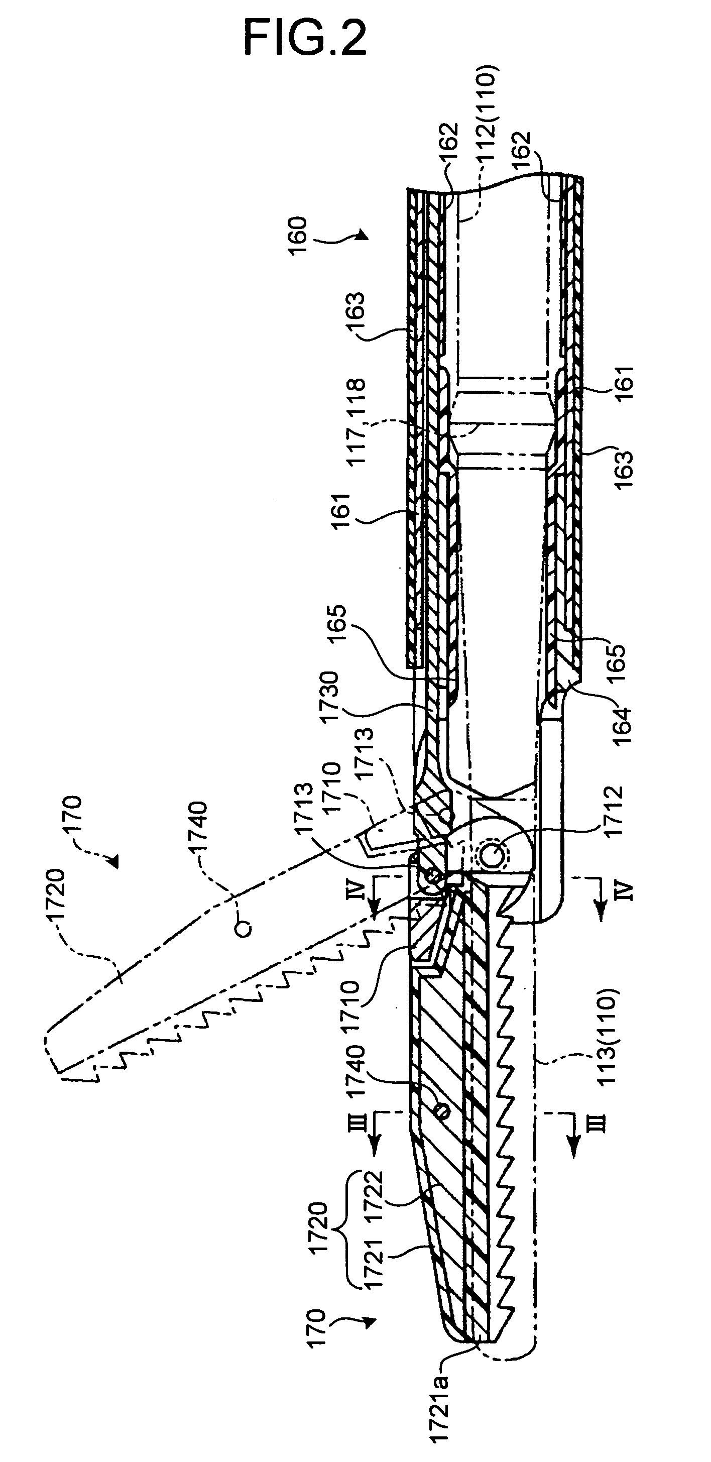
[0030]FIG. 1 to FIG. 9 are schematic diagrams for illustrating an ultrasonic treatment apparatus according to a first embodiment of the present invention. The ultrasonic treatment apparatus is employed for performing medical procedures such as cutting, removing, and coagulation of living tissues using ultrasonic wave. The ultrasonic treatment apparatus includes a vibrator 10 and a treatment unit 100 separable from each other as illustrated in FIG. 1.

[0031]The vibrator 10 includes, inside a vibrator cover 11, an ultrasonic vibrator 12 as a vibrating source. The ultrasonic vibrator 12 such as a piezoelectric element converts a given electric signal into a mechanical vibration. The ultrasonic vibrator 12 may vibrate at a frequency of 20 kilohertz or higher. The first embodiment applies one that vibrates at 47 kilohertz when the electric signal is given.

[0032]As illustrated in FIG. 1 and FIG. 5, a cable 13 is connected to the rear end of the vibrator 10 (on the right side end of the vib...

second embodiment

[0075]FIG. 10 to FIG. 14 are schematic diagrams for illustrating an ultrasonic treatment apparatus with application of an ultrasonic treatment apparatus according to a second embodiment of the present invention. As is the ultrasonic treatment apparatus described in the first embodiment, the ultrasonic treatment apparatus herein disclosed is employed for performing treatments such as cutting, removing, and coagulation of living tissues using ultrasonic waves. The configuration of a grasping member at a tip action unit is the only difference between the ultrasonic treatment apparatus herein and the apparatus according to the first embodiment.

[0076]In a grasping member 2720 applied to a treatment unit 200 of the second embodiment, a second element 2722 molded of a metal is arranged in an exposed manner on the outer surface of a first element 2721 molded of PTFE or PFA. The first element 2721 has a pinch 2721a that opposes to the treatment portion 113 of the probe 110, and a tip bearing...


PUM


Abstract

An ultrasonic treatment apparatus of the invention is provided with an improved cleaning ability and easy recyclability. A grasping member (1720) includes a first element (1721) molded of a heat resistant resin, and a second element (1722) located inside the first element (1721) as a reinforcement in such a manner that the first element (1721) covers the outer surface of the second element (1722) entirely.

Description

TECHNICAL FIELD[0001]The present invention relates to a technology for performing medical procedures such as cutting, removing, and coagulation of living tissues using ultrasonic vibration.BACKGROUND ART[0002]An example of an ultrasonic treatment apparatus for performing medical procedures such as cutting, removing, and coagulation of a living tissue using ultrasonic is disclosed in U.S. Pat. No. 6,193,709. The ultrasonic treatment apparatus includes an elongated insertion sheath that is inserted into a hollow portion of a body, a probe that is projected from a distal end of the insertion sheath, and a tip action unit that is rotatably arranged at the distal end of the insertion sheath and that moves in an opening / closing manner with respect to the probe. An operating section is provided near the proximal end of the ultrasonic treatment apparatus to operate the tip action unit rotationally.[0003]In such type of ultrasonic treatment apparatus, operation of the operating section moves...

Claims


Application Information

Patent Timeline
Patent Type & Authority Patents(United States)
IPC IPC(8): A61B18/18A61B17/32A61B17/28A61B18/14A61B19/00A61N7/02
CPCA61B17/320092A61N7/02A61B18/1445A61B2017/2825A61B2017/2829A61B2019/4868A61B2090/0813A61B2017/320093A61B2017/320095
Inventor MURAKAMI, EIJIMASUBUCHI, RYOJI
Owner OLYMPUS CORP
Learn More