Directly viewable luminaire

a direct view, luminaire technology, applied in the field of lighting, can solve the problems of reducing the reliability and life expectancy of the lighting module, generating large amounts of heat, and reducing the brightness of the luminaire, and achieve the effect of constant luminan

Active Publication Date: 2007-09-11
SIGNIFY HLDG BV
View PDF19 Cites 238 Cited by
  • Summary
  • Abstract
  • Description
  • Claims
  • Application Information

AI Technical Summary

Benefits of technology

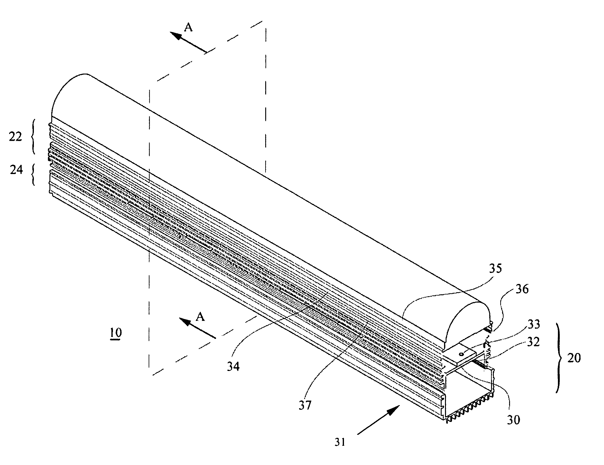
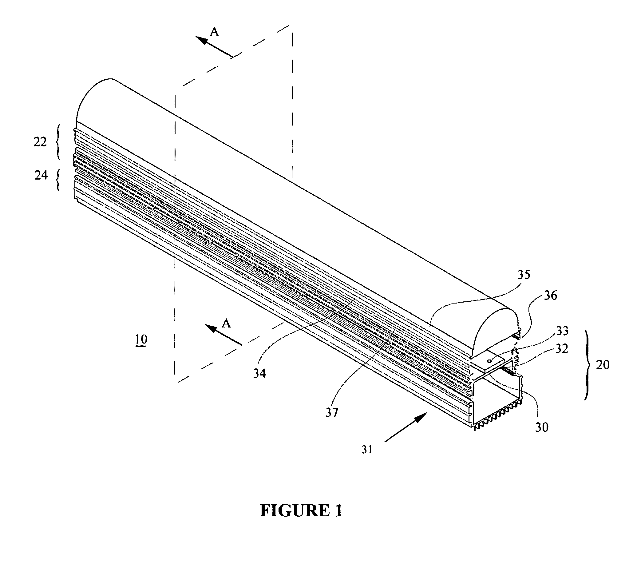
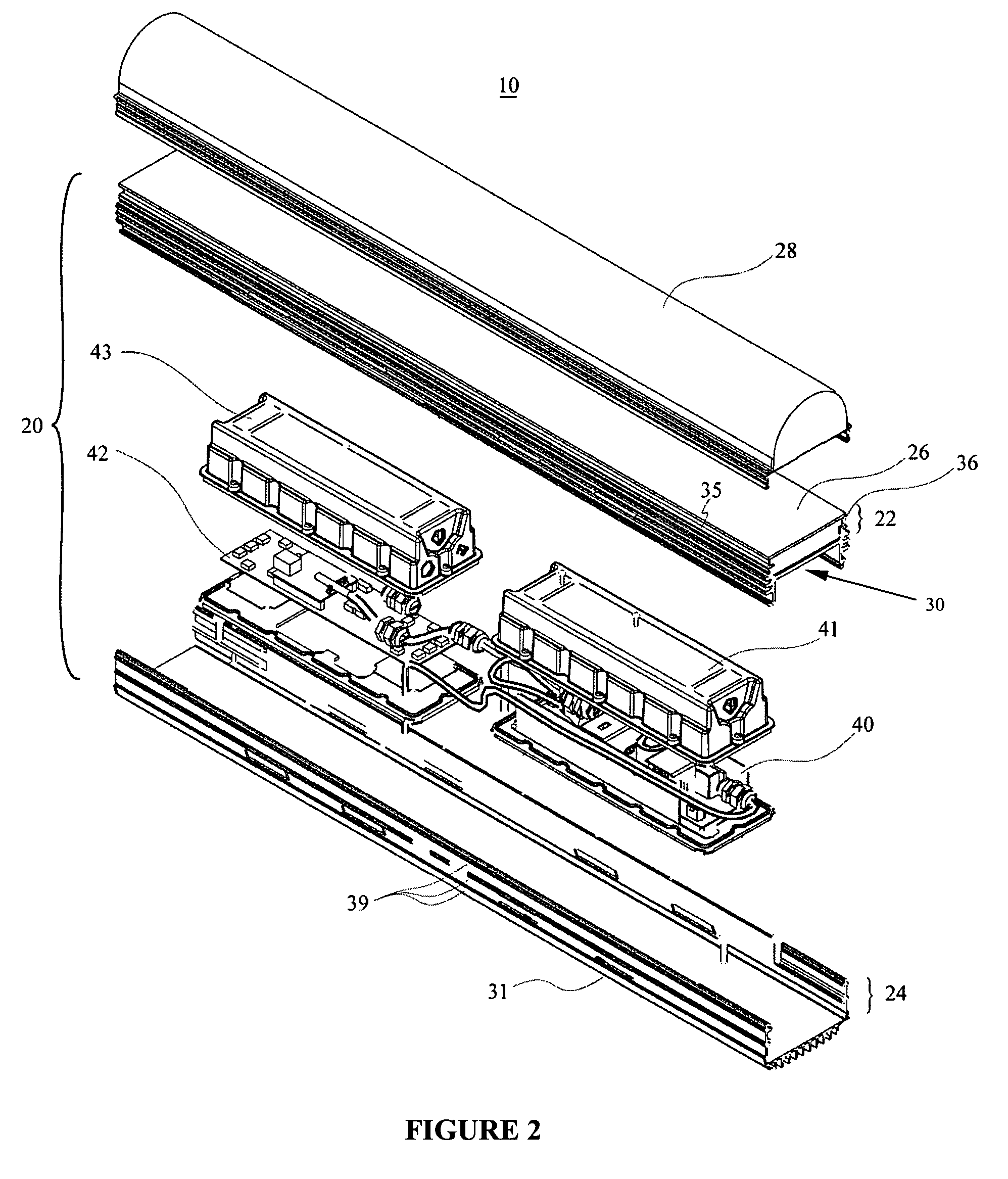
[0018]In accordance with another aspect of the present invention there is provided an optical device for use with a luminaire including two or more light-emitting elements, the optical device comprising: a first diffuser element configured to be positioned proximate to the two or more light-emitting elements, said first diffuser for diffusing emitted flux from the light-emitting elements; and a second diffuser element having a length and positioned in coaxial spaced apart alignment with the first diffuser, said second diffuser for providing secondary diffusion of the emitted flux; thereby enabling creation of a substantially constant luminance along the length of the second diffuser.

Problems solved by technology

High flux LED luminaires tend to generate large amounts of heat during operation.
Not only does this heat reduce the light output of a light-emitting diode, but it can also reduce the reliability and the life expectancy of the lighting module, due to premature failure of one or more light-emitting diodes.
Accordingly, heat dissipation often becomes a critical design consideration as the undesirable heat negatively affects the performance of the luminaire.
However, the existing heat dissipation systems generally spread the heat from a hot spot to another location for dissipation without coolth collection.
However, this heat dissipation system may not work well with housings which exhibit hot spots when dissipating heat.
The disclosed heat absorber, however, is typically a poor heat conductor and does not provide for optimal heat transfer to the heat sink.
This can further reduce light output uniformity and can cause a “pearl necklace” effect, which is undesirable.
Due to design limitations, this solution is often not available, especially when using high flux light-emitting diodes whereby the close proximity of the light-emitting diodes creates a high concentration of unwanted heat.

Method used


Image

  • Directly viewable luminaire
  • Directly viewable luminaire
  • Directly viewable luminaire

Examples


Embodiment Construction

Definitions

[0033]The term “light-emitting element” is used to define any device that emits radiation in the visible region of the electromagnetic spectrum when a potential difference is applied across it or a current is passed through it, for example, a semiconductor or organic light-emitting diode (LED or OLED, respectively) or other similar devices as would be readily understood. It would be obvious to one skilled in the art that elements that emit other forms of radiation such as infrared or ultraviolet radiation may also be used if desired in the present invention in place of or in combination with light-emitting elements.

[0034]Unless defined otherwise, all technical and scientific terms used herein have the same meaning as commonly understood by one of ordinary skill in the art to which this invention belongs.

[0035]The present invention arises from the realization that improved light output can be achieved by heat dissipation and improved light reflection. Accordingly, the degr...


PUM


Abstract

A luminaire comprising a housing having thermally separate compartments for an electronics portion and a lighting portion. These thermally separate compartments can provide thermal isolation between the electronics portion and the lighting portion. The lighting portion comprises a plurality of light-emitting elements and further includes an optical device comprising two linear diffuser elements and can be used to further improve the light emission characteristics of the light-emitting elements thereby providing a directly viewable luminaire wherein the illumination produced by point light sources appears uniform along the length of the luminaire. A power supply for supply of energy to the light-emitting elements and a controller for controlling application of energy from a power source to the light-emitting elements is provided in the electronics portion and can be thermally separated within the electronics portion.

Description

CROSS-REFERENCE TO RELATED APPLICATIONS[0001]This application claims priority to Canadian Patent Application No. 2,456,385, filed Jan. 28, 2004 and claims priority to Canadian Patent Application No. 2,462,767, filed Mar. 30, 2004; both of which are hereby incorporated herein by reference.FIELD OF THE INVENTION[0002]The present invention pertains to lighting and in particular to a directly viewable luminaire.BACKGROUND OF THE INVENTION[0003]Due to their higher overall luminous efficacy and flexibility for achieving various light patterns, luminaires using high-flux LEDs are fast emerging as the preferred lighting architecture over conventional light fixtures. These luminaires are increasingly used in a wide range of applications where high light output is required, such as theatrical spotlights, high-power flashlights, and automotive headlights. They are also penetrating mainstream commercial applications like task lights, accent lights, wall washing, signage, advertising, decorative...

Claims


Application Information

Patent Timeline
Patent Type & Authority Patents(United States)
IPC IPC(8): F21S8/04F21V29/10F21V13/00F21V15/01F21V23/00F21V29/74
CPCF21V29/89F21V5/002F21V23/02F21V29/004F21V29/15F21V29/75F21V29/763F21V29/83F21V29/87F21S48/328F21S4/003F21W2131/406F21Y2101/02F21Y2103/003F21V3/02F21V29/507F21Y2105/00F21V29/70F21V29/74F21S4/20F21Y2103/10F21Y2113/13F21Y2115/10F21Y2115/15
Inventor KAN, PETERWESTON, ADRIAN
Owner SIGNIFY HLDG BV
Why Eureka
Try Eureka